Adjusting the welding transformer. Adjusting the welding current. Simple electronic welding current regulator, diagram
One of the main components of truly high-quality welding is the correct and precise adjustment of the welding current in accordance with the task at hand. Experienced welders often have to work with metal of different thicknesses, and sometimes the standard min/max adjustment is not enough for proper work. In such cases, there is a need for multi-stage current regulation, accurate to the nearest ampere. This problem can be easily solved by connecting an additional device to the circuit - a current regulator.
The current can be adjusted in the secondary (secondary winding) and in the primary (primary winding). Moreover, each method of setting up a transformer for welding has its own characteristics that are important to consider. In this article we will tell you how to regulate the current in, we will provide diagrams of regulators for a welding transformer, and we will help you choose the right welding current regulator for the primary winding for a welding transformer.
There are many ways to regulate the current, and above we wrote about the secondary and primary windings. In fact, this is a very rough classification, since the adjustment is still divided into several components. We will not be able to analyze all the components within the framework of this article, so we will focus on the most popular ones.
One of the most commonly used current control methods is to add a secondary winding at the output. This is a reliable and durable method; you can easily make a ballast with your own hands and use it without additional equipment. Often, ballasts are used solely to reduce current.

If you are not ready to put up with these shortcomings, then we recommend that you pay attention to the method when the welding current is adjusted through the primary winding. For these purposes, electronic devices that can be easily made with your own hands are often used. Such a device will easily regulate the current through the primary and will not cause inconvenience to the welder during operation.
The electronic regulator will become an indispensable assistant for a summer resident who is forced to weld under conditions of unstable voltage. Often houses are simply not allowed to use electrical appliances larger than 3-5 kW, and this is very limiting in their work. Using the regulator, you can configure your device so that it can operate smoothly even with low voltage. Also, such a device will be useful for craftsmen who need to constantly move from place to place while working. After all, the regulator does not need to be dragged around like a ballast, and it will never cause injury.
Now we will talk about how to make an electronic regulator from thyristors yourself.
Thyristor regulator circuit
![]()
Above you can see a diagram of a simple regulator using 2 thyristors with a minimum of non-scarce parts. You can also make a regulator using a triac, but our practice has shown that a thyristor power regulator is more durable and operates more stably. The assembly diagram is very simple and according to it you can quickly assemble the regulator with minimal soldering skills.
The operating principle of this regulator is also simple. We have a primary winding circuit into which the regulator is connected. The regulator consists of transistors VS1 and VS2 (for each half-wave). The RC circuit determines the moment when the thyristors open, and at the same time the resistance R7 changes. As a result, we get the opportunity to change the current in the primary of the transformer, after which the current changes in the secondary.
Pay attention! The regulator is adjusted under voltage, do not forget about this. To avoid fatal mistakes and avoid injury, it is necessary to isolate all radio elements.
In principle, you can use old-style transistors. This is a great way to save money, since these transistors can easily be found in an old radio or at a flea market. But keep in mind that such transistors must be used at an operating voltage of at least 400 V. If you find it necessary, you can use dinistors instead of the transistors and resistors shown in the diagram. We did not use dinistors, since in this version they do not work very stably. In general, this thyristor-based welding current regulator circuit has proven itself well, and on its basis many regulators have been manufactured that operate stably and perform their function well.
You could also see the RKS-801 regulator and the RKS-15-1 resistance welding regulator in stores. We do not recommend making them yourself, since it will take a lot of time and will not save you much money, but if you want, you can make RKS-801. Below you see a diagram of the regulator and a diagram of its connection to the welder. Open the pictures in a new window to see the text better.
Welding current measurement
Once you have made and configured the regulator, it can be used in operation. To do this, you need another device that will measure the welding current. Unfortunately, it will not be possible to use household ammeters, since they are not capable of handling more than 200 amperes. Therefore, we recommend using a clamp meter. This is a relatively inexpensive and accurate way to find out the current value; the clamp control is clear and simple.
The so-called “clamps” at the top of the device grip the wire and measure the current. There is a current measurement limit switch on the device body. Depending on the model and price, different manufacturers make clamp meters capable of operating in the range of 100 to 500 amps. Choose a device whose characteristics match yours.
Clamp meters are an excellent choice if you need to quickly measure the current value without affecting the circuit or connecting additional elements to it. But there is one drawback: clamps are absolutely useless when measuring . The fact is that direct current does not create an alternating electromagnetic field, so the device simply does not see it. But when working with such a device, it meets all expectations.
There is another way to measure current, it is more radical. You can add an industrial ammeter to the circuit of your semi-automatic welding machine, capable of measuring large current values. You can also simply temporarily add an ammeter to the open circuit of the welding wires. On the left you can see a diagram of such an ammeter, according to which you can assemble it.
This is a cheap and effective way to measure current, but using an ammeter in welding machines also has its own characteristics. It is not the ammeter itself that is added to the circuit, but its resistor or shunt, and the dial indicator must be connected in parallel to the resistor or shunt. If you do not follow this sequence, the device, at best, simply will not work.
Instead of a conclusion
Regulating the welding current on a semi-automatic machine is not as difficult as it might seem at first glance. If you have minimal knowledge in the field of electrical engineering, you can easily assemble a current regulator for a welding machine using trimistors on your own, saving on the purchase of this device in a store. Homemade regulators are especially important for home craftsmen who are not ready to spend additional money on equipment. Tell us about your experience in making and using a current regulator in the comments and share this article on your social networks. We wish you good luck in your work!


I recently came across on the Internet an interesting diagram of a simple but quite good entry-level power supply capable of delivering 0-24 V at a current of up to 5 amperes. The power supply provides protection, that is, limiting the maximum current in case of overload. The attached archive contains a printed circuit board and a document that describes the configuration of this unit, and a link to the author’s website. Please read the description carefully before assembling.

Here is a photo of my version of the power supply, a view of the finished board, and you can see how to roughly use a case from an old ATX computer. The adjustment is made 0-20 V 1.5 A. Capacitor C4 for this current is set to 100 uF 35 V.

When there is a short circuit, the maximum limited current is output and the LED lights up, bringing the limiter resistor to the front panel.
Power supply indicator
I carried out an audit and found a pair of simple M68501 pointer heads for this power supply. I spent half a day creating a screen for it, but I finally drew it and fine-tuned it to the required output voltages.

The resistance of the indicator head used and the resistor used are indicated in the attached file on the indicator. I’m laying out the front panel of the unit, if anyone needs to remodel the case from an ATX power supply, it will be easier to rearrange the inscriptions and add something than to create from scratch. If other voltages are required, the scale can simply be calibrated, this will be easier. Here is a finished view of the regulated power supply:

The film is a self-adhesive "bamboo" type. The indicator has a green backlight. Red LED Attention indicates that overload protection has been activated.

Add-ons from BFG5000
The maximum limiting current can be made more than 10 A. On the cooler - 12 volts plus a temperature speed controller - from 40 degrees the speed begins to increase. The circuit error does not particularly affect the operation, but judging by the measurements during a short circuit, there is an increase in the passing power.

The power transistor was installed 2n3055, everything else is also foreign analogues, except for BC548 - installed KT3102. The result was a truly indestructible power supply. Just the thing for beginner radio amateurs.

The output capacitor is set to 100 uF, the voltage does not jump, the adjustment is smooth and without visible delays. I set it based on the calculation as indicated by the author: 100 microfarads of capacity per 1 A of current. Authors: Igoran And BFG5000.
Discuss the article POWER SUPPLY WITH CURRENT AND VOLTAGE REGULATION
The quality of the weld depends largely on the characteristics of the electric arc. For each thickness of metal, depending on its type, a certain force is required.
In addition, the current-voltage characteristic of the welding machine is important; the quality of the electric arc depends on it. Cutting metal also requires its own electric current values. That is, any welding machine must have a regulator that controls the welding power.
The current can be controlled in different ways. The main methods of regulation are:
- introducing a resistive or inductive load into the secondary winding of the welding machine;
- changing the number of turns in the secondary winding;
- change in the magnetic flux of the welding machine;
- use of semiconductor devices.
There are many schematic implementations of these methods. When making a welding machine with your own hands, everyone can choose a regulator according to their taste and capabilities.
Resistor or inductance
 Adjusting the welding current using a resistance or inductor is the simplest and most reliable. A powerful resistor or inductor is connected in series. Due to this, the active or inductive resistance of the load changes, which leads to a voltage drop and a change in the welding current.
Regulators in the form of resistors are used to improve the current-voltage characteristics of the welding machine. A set of powerful wire resistances or one resistor made of thick nichrome wire in the form of a spiral is used.
To change the resistance, they are connected to a specific turn of wire using a special clamp. The resistor is made in the form of a spiral to reduce its size and ease of use. The resistor value should not exceed 1 ohm.
Alternating current at certain times has zero or close to it values. At this time, a short-term arc extinguishing occurs. When the gap between the electrode and the part changes, sticking or complete extinguishing may occur.
To soften the welding mode and, accordingly, obtain a high-quality seam, a regulator is used in the form of a choke, which is connected in series with the holder in the output circuit of the device.
The additional inductance causes a phase shift between the output current and voltage. At zero or close to zero values of alternating current, the voltage has a maximum amplitude and vice versa. This allows you to maintain a stable arc and ensures reliable ignition.
The choke can be made from an old transformer. Only its magnetic core is used, all windings are removed. Instead, 25-40 turns of thick copper wire are wound.
This regulator was widely used when using AC transformer devices due to its simplicity and availability of components. The disadvantages of the welding current throttle regulator are the small control range.
Changing the number of turns
 With this method, the arc characteristics are adjusted by changing the transformation ratio. The transformation ratio can be changed by additional taps from the secondary coil. By switching from one tap to another, you can change the voltage in the output circuit of the device, which leads to a change in arc power.
The regulator must withstand high welding current. The disadvantage is the difficulty of finding a switch with such characteristics, a small range of adjustments and discreteness of the transformation ratio.
Magnetic flux change
 This control method is used in transformer welding machines. By changing the magnetic flux, the efficiency of the transformer is changed, this in turn changes the value of the welding current.
The regulator works by changing the gap of the magnetic circuit, introducing a magnetic shunt or moving the windings. By changing the distance between the windings, the magnetic flux is changed, which accordingly affects the parameters of the electric arc.
On older welding machines there was a handle on the lid. As it rotated, the secondary winding was raised or lowered by a worm gear. This method has practically become obsolete; it was used before the proliferation of semiconductors.
Semiconductor devices
The creation of powerful semiconductor devices capable of operating with high currents and voltages has made it possible to develop a new type of welding machines.
They have become capable of changing not only the resistance of the secondary circuit and phase, but also changing the frequency of the current and its shape, which also affects. A traditional transformer welding machine uses a welding current regulator based on a thyristor circuit.
Adjustment in inverters
 Welding inverters are the most modern devices for electric arc welding. The use of powerful semiconductor rectifiers at the input of the device and the subsequent transformation of alternating current into direct current, and then into high-frequency alternating current, made it possible to create devices that are compact and powerful at the same time.
In inverter devices, the main regulator is changing the frequency of the master generator. For the same transformer size, the conversion power directly depends on the frequency of the input voltage.
The lower the frequency, the less power is transferred to the secondary winding. The adjustment resistor knob is displayed on the front panel of the inverter. When it rotates, the characteristics of the master oscillator change, which leads to a change in the switching mode of the power transistors. The result is the required welding current.
When using inverter semi-automatic welding machines, the settings are the same as when using manual welding.
In addition to external regulators, the inverter control unit contains many different control elements and protections that ensure a stable arc and safe operation. For a novice welder, the best choice would be an inverter welding machine..
Application of thyristor and triac circuits
 After the creation of powerful thyristors and triacs, they began to be used in output current regulators in welding machines. They can be installed in the primary winding of the transformer or in the secondary winding. The essence of their work is as follows.
The control contact of the thyristor receives a signal from the regulator circuit that opens the semiconductor. The duration of the signal can vary within wide limits, from 0 to the duration of the half-cycle of the current flowing through the thyristor.
The control signal is synchronized with the regulated current. Changing the signal duration causes the beginning of each half-cycle of the welding current sinusoid to be cut off. The duty cycle increases, as a result the average current decreases. Transformers are very sensitive to such control.
This regulator has a significant drawback. The time of zero values increases, which leads to uneven arc and its unauthorized extinguishing.
To reduce the negative effect, it is additionally necessary to introduce chokes, which cause a phase shift between current and voltage. In modern devices this method is practically not used.
When using direct current in technology, it is necessary to smoothly and widely regulate the current strength in the consumer circuit. The fundamentally possible rheostat control is extremely uneconomical due to large energy losses in rheostats. Therefore, for several decades in technology, more economical ion devices have been widely used - mercury valves, thyratrons, ignitrons, etc. - devices with control grids.
Currently, nonlinear elements (controlled semiconductor valves) - thyristors - are widely used for these purposes. They are compact, economical and have good performance. Thyristor rectifiers and converters are being very intensively introduced into electrical equipment in a wide variety of industries and especially into the system of all types of electrified transport (railroads, metro, trolleybus, tram). With the help of thyristors, you can not only rectify alternating current and regulate its average value, but also regulate the current strength and voltage in alternating current circuits.
Figure 4-19 shows the circuit and principle of regulating the average (over half a cycle) value of the rectified voltage using a controlled thyristor, depending on the timing of the supply of control pulses. Voltage pulses across the load have different durations. So, if control pulses are applied at the beginning of each half-cycle, then the voltage across the load is the same as in a conventional full-wave circuit. If pulses are applied in the middle of each half-cycle, then the rectified voltage pulses will have a duration equal to a quarter of the period, etc.
Figure 4-20 shows voltage regulation similar to the previous one, but in an alternating current circuit. Here in every


half of the period, the current passes through one pair of diodes (without rectification) and through the thyristor T. By influencing the thyristor with special control pulses, it is possible to transform a sinusoidal voltage (and current) into a sequence of pulses of any duration, amplitude and polarity, i.e., the effective value of the voltage can be adjusted (and current) over a wide range.
Finally, Figure 4-21 shows a diagram of rectification and current regulation with a three-phase thyristor rectifier. Here the LU is an automatic device that supplies pulses at moments of the period corresponding to regulation, and the thyristors rectify the alternating current and at the same time regulate its average value.
Many modern devices have the ability to adjust their parameters, including current and voltage values. Due to this, you can configure any device in accordance with specific operating conditions. For these purposes, there is a current regulator available in various configurations and designs. The adjustment process can occur with both direct and alternating current.
The main operating elements of regulators are thyristors, as well as various types of capacitors and resistors. In high-voltage devices, magnetic amplifiers are additionally used. Modulators ensure smooth adjustments, and special filters help smooth out interference in the circuit. As a result, the electric current at the output becomes more stable than at the input.
Current and voltage regulator
DC and AC regulators have their own characteristics and differ in their main parameters and characteristics. For example, a DC voltage regulator has higher conductivity with minimal heat loss. The basis of the device is a diode-type thyristor, which provides a high pulse supply due to accelerated voltage conversion. Resistors used in the circuit must withstand a resistance value of up to 8 ohms. Due to this, heat losses are reduced, protecting the modulator from rapid overheating.
The DC regulator can function normally at a maximum temperature of 40 0 C. This factor must be taken into account during operation. Field-effect transistors are located next to thyristors, since they only pass current in one direction. Due to this, the negative resistance will be maintained at a level not exceeding 8 ohms.
The main difference of the current regulator is the use of exclusively triode-type thyristors in its design. However, field-effect transistors are used the same as in DC regulators. Capacitors installed in the circuit perform only stabilizing functions. High-pass filters are very rare. All problems associated with high temperatures are solved by installing pulse converters located next to the modulators. AC regulators whose power does not exceed 5 V use low-pass filters. Cathode control in such devices is performed by suppressing the input voltage.
During adjustments in the network, smooth operation must be ensured. At high loads, the circuit is supplemented with reverse direction zener diodes. To connect them together, transistors and an inductor are used. Thus, the current regulator on the transistor performs current conversion quickly and losslessly.

Special attention should be paid to current regulators designed for active loads. The circuits of these devices use triode-type thyristors, capable of passing signals in both directions. The anode current in the circuit decreases during the period when the maximum frequency of this device decreases. The frequency may vary within the limits set for each device. The maximum output voltage will depend on this. To ensure this mode, field-type resistors and conventional capacitors capable of withstanding resistance up to 9 Ohms are used.
Very often, such regulators use pulsed zener diodes that are capable of overcoming the high amplitude of electromagnetic oscillations. Otherwise, as a result of a rapid increase in the temperature of the transistors, they will immediately become inoperative.
Voltage and current regulator circuit
Before considering the voltage regulator circuit, it is necessary to at least become familiar with the principle of its operation. As an example, we can take voltage, which is widespread in many circuits.
The main part of such devices as the welding current regulator is the thyristor, which is considered one of the powerful semiconductor devices. It is best suited for high power energy converters. The control of this device has its own specifics: it opens with a current pulse, and closes when the current drops almost to zero, that is, below the holding current. In this regard, thyristors are mainly used to operate with alternating current.

You can regulate alternating voltage using thyristors in different ways. One of them is based on skipping or prohibiting entire periods or half-cycles from the controller output. In another case, the thyristor turns on not at the beginning of the voltage half-cycle, but with a slight delay. At this time, the output voltage will be zero, and accordingly no power will be transferred to the output. In the second part of the half-cycle, the thyristor will already conduct current and voltage will appear at the output of the regulator.
The delay time is also known as the opening angle of the thyristor. If it is set to zero, all input voltage will go to the output and the voltage drop across the on-SCR will be lost. When the angle begins to increase, the output voltage will decrease under the action of the thyristor regulator. Therefore, if the angle is 90 electrical degrees, the output will be only half the input voltage, but if the angle is 180 degrees, the output voltage will be zero.
The principles of phase regulation make it possible to create not only a current and voltage regulator for the charger, but also stabilization, regulation, and soft start circuits. In the latter case, the voltage increases gradually, from zero to the maximum value.

Based on the physical properties of thyristors, a classic current regulator circuit was created. In the case of using coolers for diodes and a thyristor, the resulting regulator will be able to supply up to 10 A to the load. Thus, at a voltage of 220 volts, it becomes possible to regulate the voltage on a load with a power of 2.2 kW.
Such devices consist of only two power components - a thyristor and a diode bridge, designed for a current of 10 A and a voltage of 400 V. The diode bridge converts alternating voltage into a unipolar pulsating voltage. Phase adjustment of half-cycles is performed using a thyristor.
To limit the voltage, two resistors and a zener diode are used. This voltage is supplied to the control system and is 15 volts. The resistors are connected in series, thereby increasing the breakdown voltage and power dissipation. Based on the simplest parts, you can easily make homemade current regulators, the circuit of which will be quite simple. As a specific example, it is worth taking a closer look at the thyristor welding current regulator.
Diagram of a thyristor welding current regulator
The principles of arc welding are known to everyone who has encountered welding work. To obtain a welding connection, you need to create an electric arc. It occurs at the moment when voltage is applied between the welding electrode and the material being welded. Under the action of the arc current, the metal melts, forming a kind of molten bath between the ends. When the seam cools, both metal parts are firmly connected to each other.

In our country, the alternating current frequency is 50 Hz, the phase supply voltage is 220 V. Each welding transformer has two windings - primary and secondary. The transformer secondary voltage or secondary voltage is 70V.
Welding can be carried out manually or automatically. At home, when you create a current and voltage regulator with your own hands, welding work is performed manually. Automatic welding is used in industrial production for large volumes of work.
Manual welding has a number of parameters that are subject to change and adjustment. First of all, this concerns the strength of the welding current and arc voltage. In addition, the speed of the electrode, its brand and diameter, as well as the number of passes required per seam may vary. In this regard, the correct selection of parameters and maintaining their optimal values throughout the entire welding process is of great importance. Only in this way can a high-quality welded joint be ensured.

Changing the current during welding can be done in various ways. The simplest of them is to install passive elements in the secondary circuit. In this case, a resistor or inductor is connected in series to the welding circuit. As a result, the arc current and voltage changes due to the resistance and the resulting voltage drop. Additional resistors allow you to soften the current-voltage characteristics of the power supply. They are made from nichrome wire with a diameter of 5-10 mm. This method is most often used when it is necessary to make a current regulator. However, this design has a small range of adjustments and difficulties in adjusting parameters.
The next adjustment method involves switching the number of turns of transformer windings. Due to this, the transformation coefficient changes. These regulators are easy to manufacture and operate; you just need to make taps when winding the turns. For switching, a switch is used that can withstand high current and voltage values.
Often adjustments are made by changing the magnetic flux of the transformer. This method is also used when you need to make a current regulator yourself. In this case, adjustment is made by moving the windings, changing the gap, or introducing a magnetic shunt.
 What documents are evidence that the apartment is a service apartment?
 Space donut hole
 Types of discounts on Russian Railways tickets and rules for obtaining them Train tickets for students
 Lecture on syndromic pathology
 Organizational aspects of the activities of pharmacy organizations
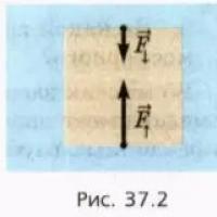 Water Pressure in the Deep Ocean Practice Reports
 What is inductance, its definition and unit of measurement