Calculation of foundation cubic capacity online. Foundation calculation. What can an online calculator calculate?
In construction, there are a large number of types of foundations, different in their design features, construction methods and source materials.
The monolithic type is divided into subtypes: shallow and deep.
When building a small house, a monolithic foundation can only be equipped with additional labor, or, in extreme cases, the help of friends.
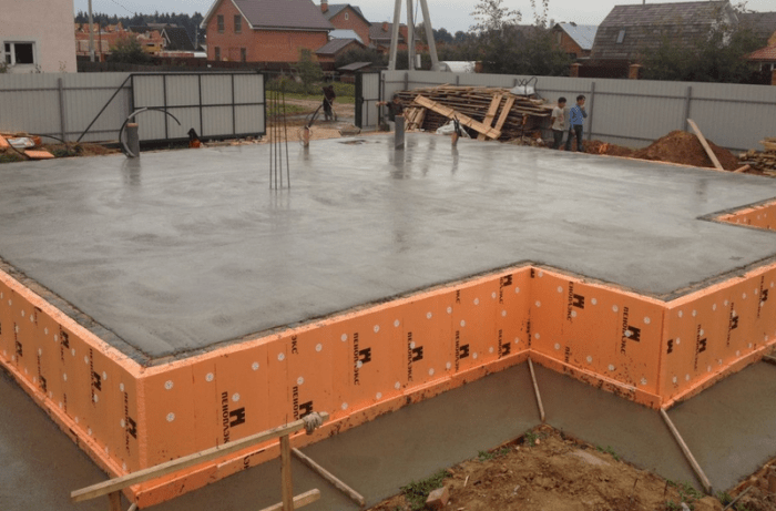
Construction of a monolithic foundation
The great advantage of the monolithic type of base is its unique ability to be installed on absolutely any surface. Even if the surface of the construction site is soil that is uneven in structure, with areas of peat bogs and sand cushions, then a monolithic foundation, represented by a concrete slab and formwork, can withstand any load of the future building.
The monolithic foundation is very resistant to loads, even those that arise due to soil subsidence. This feature is ensured by a large support area, which significantly reduces the pressure on the soil.
The negative characteristics of a monolithic base include:
- high consumption of expensive materials;
- massiveness of the structure;
- large labor costs during construction of the structure.
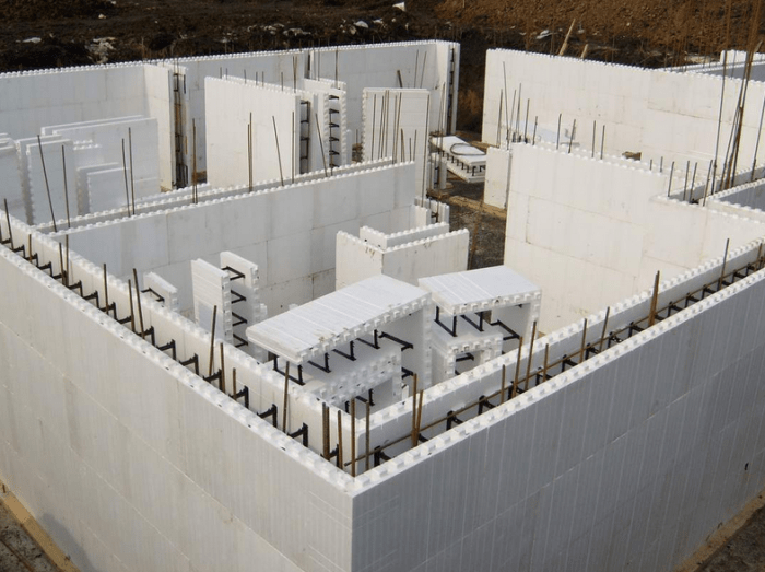
Unlike other types of foundation, a monolithic foundation requires reinforcement throughout the entire structure. It is usually carried out by reinforcing the surface. This approach also allows you to cope with possible loads arising from soil movement.
Traditionally, a monolithic foundation is used in the construction of those buildings in which the functions of the foundation are taken over by the surface of the first floor.
Attention ! The use of monolithic foundations makes it possible to implement a large number of architectural projects of modern buildings.

Calculation of a monolithic foundation
The level of strength of the house and the duration of its operation depend on how accurate the calculation results are. For all the main indicators of a monolithic foundation, it is worth carrying out calculations at the development stage of a construction project.
First of all, we determine the level of load that the selected type of foundation and the soil on which the foundation will press can withstand. There are temporary and permanent types of load. Constants include the weight of the foundation, roof and walls, and also take into account the weight of furniture, equipment located in the house, and the people living in it.

Variable loads are somewhat more difficult to calculate, since these are the weather and climatic conditions that prevail on the territory of the constructed building.
Before starting to calculate the foundation, experts calculate the area of support on which it will be located. It is imperative to calculate the mass of the monolithic foundation, since exceeding the load on the ground can lead to a rather disastrous situation.
Important ! When carrying out calculations, experts pay special attention to the building materials that will be used in the construction of the house. This approach makes it possible to correctly assess the real load and correctly distribute it over the entire area of the house.

Thickness of monolithic foundation
Calculation of the thickness indicator should be carried out taking into account:
- soil indicators;
- geodesy of the site;
- technological features of the construction project.
Taking these parameters into account, the thickness and area of the monolithic base are calculated. Let us consider the features of using a monolithic base depending on the thickness index.
With a minimum value of 15 cm, a monolithic base is suitable only for light, small buildings erected on non-heaving soil. The ideal option is a foundation thickness of 20-30 cm. This is the optimal parameter for the construction of knowledge, regardless of the materials used and the types of soil at the construction site.

If the project provides additional protection from low temperatures, then the foundation is insulated with foam plastic plates and, accordingly, when making calculations, the thickening of the edge must be taken into account. The frost-resistant type of monolithic base is made of reinforced concrete slab. It is irrational to use a base with a thickness of more than 30 cm.
The thickness of the strip foundation walls must be at least 35cm. If the construction site is dominated by loose soils, it is necessary to expand the base of the foundation by arranging several ledges in order to reduce pressure on the soil. The width of the erected elements should be about 20 cm, the height indicator should be about 30-40 cm. The edge of the strip foundation must exceed the level of the ground surface.

Calculation for a monolithic strip foundation
To begin with, we determine the following dimensions: the width of the walls, the perimeter of the future building and the height of the foundation pouring. Each of these indicators is necessary for the correct calculation of the casting volume.
Let's start with the calculation:
Let's find the height of the foundation. To do this, we use the following formula:
F ≥ Z + 10 cm ., where F is an indicator of the height of the foundation, and Z is a unit of column embedding depth.
Important ! The height of the foundation should be greater than or equal to the length of the reinforcement used to strengthen the concrete pour.

Then we calculate the volume of the casting. To do this, we use the following formula:
V excellent = b × P × F , where b is the width of the walls, P is the perimeter of the base, F is the height of the casting.
V = ( b × l × F ) - V excellent ,where b is the width of the walls, l- foundation length F - casting height, V ex - casting volume.
It is also necessary to calculate the formwork. To do this, the first step is to determine the area of the side surfaces. After this, we find the area of the side walls; to do this, we multiply the perimeter of the base by 2 and multiply by the height of the casting. At the next stage, the area of one board is determined:
S boards = b × l , where b is the width of the board, and l- length of the board.
Amount of lumber = S side surfaces / S one board.

Let's consider the calculation of a monolithic strip foundation using an example. Let us assume that the foundation has the following initial data:
- length -15m;
- width - 3.8m;
- casting height - 0.3 m;
- casting height - 0.18 m.
Based on these data, we determine the volume of the casting using the previously discussed formula. We get that V ex = (15*2+3.8*2)*0.18*0.3 = 2.03m3.
Now let's determine the volume of the internal part V = (3.8*15*0.3) - 2.03 = 15.07 m3.
As a result of the calculations, we determined that the volume of the casting is 2.03 m3, and the volume for filler is 15.07 m3.
Conclusion
The technological process of arranging a monolithic foundation is very complex and expensive. But it is strictly unacceptable to make any changes to the calculations of materials in order to save money. Otherwise, such activities can lead to very disastrous results. The erected structure will be so fragile and of poor quality that it is unlikely to be able to withstand the load of the building. As a result, complete or partial destruction of the erected structure is possible.
Therefore, calculations of the main parameters of a monolithic foundation must be carried out with strict adherence to all recommendations, and in case of controversial situations, you need to seek help from specialists.
In the next video we will look at typical mistakes when reinforcing and concreting a monolithic strip foundation
| Concrete grade | Material ratio (Cement x Sand x Crushed stone) | Consumption of Cement per 1m3 of benon (kg.) |
| M-100 | 1 x 4.6 x 7.0 | 170 |
| M-150 | 1 x 3.5 x 5.7 | 200 |
| M-200 | 1 x 2.8 x 4.8 | 240 |
| M-250 | 1 x 2.1 x 3.9 | 300 |
| M-300 | 1 x 1.9 x 3.7 | 320 |


Note: accurate concrete calculations are carried out for dry sand and crushed stone; if they are moistened, the volume of water will be different. Here you need to experiment with the volume of water.
Foundation base width A- depends on the weight of the building, the strength characteristics of the soil under the building, etc. It is recommended to accept based on the calculation results.
The width of the roof must be increased.
H- height of the foundation. Depends on the degree of soil subsidence (the more subsidence the soil, the higher)
HC- the height of the foundation (basement) above ground level. The required formwork area depends on it. The excess level should not be less than 200 mm.
The depth of the foundation into soil subject to frost heaving (loams, clays) should be no less than the depth of soil freezing in the given region. The depth should be no less than the thickness of the plant soil layer (30-50 cm)
In underground soils, the walls of the trench are unstable and will crumble.
Horizontal rows of reinforcement are made from “working” reinforcement with a diameter of more than 10 mm, and vertical rows are made from “structural” reinforcement with a diameter of 8-10 mm of smooth or periodic section.
The pitch of vertical reinforcement is taken from the conditions of non-sagging of the working reinforcement of the upper row.
It is prohibited to insert vertical reinforcement into the ground or install it on pieces of crushed stone and other improvised objects. The reinforcement frame must either be suspended or installed on specially made concrete support cubes.
The distance between the ends of the reinforcement must be at least 15 mm.
Since a strip foundation for a house is a closed loop of reinforced concrete beams erected under all the load-bearing walls of the house, choose one of the eight proposed standard foundation options based on how many load-bearing walls are planned in the house.
Option No. 1 is relevant if construction is planned without internal supporting walls, No. 2 if an internal supporting wall is needed, options No. 3-8 if more load-bearing walls are needed in the house.
Fill in the dimensions in millimeters:
X– The width of the foundation depends on your wishes and the possibility of construction on the site. Parameter value X take more than the width of the walls (i.e. the distance between the outer planes of the walls) by approximately 100 mm on each side to allow finishing. When you select the option X SP 50-101-2004 “Design and installation of foundations and foundations of buildings and structures” should be taken into account.
A shallow strip foundation is suitable for all types of soil except subsidence, peat bogs and water-saturated soils. And it is often optimal for frame, timber, and brick houses.
Y– the length of the strip foundation is determined by the length of the house.
H– The height of the foundation depends on the depth of the foundation (shallow from 0.3-1 m, buried up to 2-3 m) and the elevation above ground level. The foundation must be made below the freezing line and above the groundwater level. If it is not planned to equip auxiliary premises in the basement, then a height of about 150-300 mm above ground level is sufficient, and if the base is to be used, more. The height of the strip foundation H is taken from 0.3 m for light houses and reaches about 4 m for heavy stone ones. The key to a reliable foundation is an individual project that takes into account the characteristics of the soil on the site; height of groundwater; the depth of soil freezing in your region; the weight of the house (i.e. the load on the foundation from the weight of the walls, ceilings and roof).
A– thickness of the foundation strip, i.e. the distance between the outer and inner planes of the foundation depends on the thickness of the walls being built (accepted to be 100-150 mm more). Approximate values of the thickness of the strip foundation for outbuildings (shed, bathhouse, garage) are in the range of 250-400 mm; for a 1-story light (for example, frame) house 300-650 mm; A 2-storey brick house is built on a foundation 650-750 mm thick.
WITH– the center-to-center distance between the foundation lintels (relevant for options No. 2-No. 8) depends on the features of your project.
Reinforcement parameters:
G– Number of horizontal reinforcing rows, for strip foundation G=2. It may be more depending on the magnitude of the existing loads. It is recommended that you familiarize yourself with SP 63.13330.2012. The capabilities of the online calculator allow you to calculate up to 10 rows of reinforcement.
V– The number of vertical rods connecting the reinforcing belts to each other can be from 1 to 5.
Z– The number of connecting rods is taken from 1 to 5.
S– Step length is the distance between adjacent vertical reinforcing straps. Optimal value S 300-500 mm.
Weight of 1 m reinforcement depends on its diameter. The approximate weight of one meter of different diameters of iron reinforcement is given in the table.
| Diameter fittings, mm |
Weight of 1 linear meter of reinforcement, kg |
| 6 | 0,222 |
| 8 | 0,395 |
| 10 | 0,617 |
| 12 | 0,888 |
| 14 | 1,21 |
| 16 | 1,58 |
| 18 | 2 |
| 20 | 2,47 |
| 22 | 2,98 |
| 25 | 3,85 |
| 28 | 4,83 |
| 32 | 6,31 |
Formwork parameters:
Board thickness for assembling formwork, it is taken from 25 mm to 50 mm on the basis that the thicker the better (but also more expensive).
Board length. This parameter is usually selected around 4000-6000 mm, depending on the availability of lumber in the warehouse and the price of the formwork board.
The board is wide. To make formwork, use an edged board (possible on one side) with a width of 100-200 mm.
Installation of formwork requires care and a responsible attitude of performers in order to ensure the correct geometry of the future foundation.
It is important to strengthen the assembled formwork with wire so that it does not fall apart due to the weight of the concrete, cover the inside with plastic film, this will prevent concrete leakage and make it possible to reuse the boards for construction purposes.
Concrete composition parameters:
Bag weight, kg– here enter how much 1 bag of cement weighs in kilograms.
Concrete proportions by weight. The approximate ratio of components for a concrete mixture is 2-3 parts sand for 1 part cement, 4-5 parts crushed stone, 1/2 part water (the mixture should be plastic and not too liquid). However, depending on the required grade of concrete, the grade of cement used, the characteristics of sand, crushed stone, the use of plasticizers or additives, the proportions may vary. Standard rates of cement consumption for the preparation of prefabricated and monolithic concrete, reinforced concrete products and structures are regulated by SNiP 5.01.23-83.
Enter prices for building materials: cement (per bag), sand (per 1 ton), board (per 1 cubic meter) and reinforcement (per 1 ton).
This construction calculator will:
- calculation of the base area of the strip foundation and the required volume of concrete for pouring it;
- calculation of the formwork area (i.e. the area of the side surfaces) and the required amount of lumber for the formwork of a strip foundation and their price (if the height of the slab is not a multiple of the height of the board, then the number of boards is calculated taking into account covering the entire height of the slab);
- calculation of the number of bags of cement, tons of sand and crushed stone for a strip foundation and the cost of these components of concrete for pouring;
- calculation of the required reinforcement of a strip foundation, namely the number of horizontal, vertical and connecting rows of reinforcement, its length, weight and cost of reinforcement.
The calculator will also calculate the final cost of constructing a strip foundation, which will give an idea of the level of material investment in the foundation of your home and allow you to make an informed decision about the feasibility of this type of foundation. You can also calculate other foundation options using our calculators and choose the optimal solution.


When building a house, one of the important components of competent organization of the entire process is the correct calculation of the amount of materials used. Of course, all stages of construction are important, but one of the first to be calculated is the foundation, namely the amount of materials that will need to be spent when pouring it. At the same time, if accurate calculations are obtained in specialized programs or manually, then approximate figures will be given by an online calculation of the strip foundation of a house - if its geometry is not too complex, then this data will be quite sufficient.

One of the interface options for the online foundation calculator
Online foundation calculator
To find out the approximate cost of a strip foundation, use the following calculator:
What can an online calculator calculate?
You must understand that any automatic calculation of the foundation online calculator can produce with a certain error. Its value depends at least on whether a simple formula is used to calculate the volume, or whether it additionally takes into account the correction factors derived to calculate the amount of concrete. Additionally, the difference in the geometry of a standard rectangular foundation or one designed for additional load-bearing walls inside the perimeter must be taken into account.
As a result, the websites post either a free calculator for the cost of the foundation as a whole, or programs that calculate its individual parameters - the volume of concrete, the amount of reinforcement, as well as the boards that are needed to create the formwork. Along with the boards, you must not forget to count the beams for the spacers and the nails with which it will all be fastened.
You also need to remember that online calculations will never give a 100% guarantee of the correctness of the result, because on the website you need to enter the required data and the program will simply display the final result of the calculations without any explanation. So that you don’t have to take them all on faith, you need to understand with the help of what formulas and data you can double-check the result of online calculations.
Video description
An example of using an online calculator in the video:
Calculation of the volume of concrete that will be poured into the foundation
When using online calculators, it is assumed that all loads have already been calculated for the foundation. This means that it is calculated how many bricks will go on the walls and how much weight will put pressure on the base. You also need to take into account the impact of wind loads and the weight of snow that will lie on the roof in winter. Simply put, all the calculations have already been made, the user has decided on the linear dimensions and now you just need to calculate the amount of concrete that will be poured.
Here it is necessary to take into account a number of nuances, ignoring which will lead to ordering insufficient or excessive quantities of concrete:
Linear dimensions of the foundation
At first glance, calculating a strip foundation is simple - take the length, width and depth, multiply everything and get the volume. The nuance here is that this method works ideally for a straight line, but since the foundation is at least rectangular, serious errors creep into the calculations.
For example, the simplest case is a 6x8 foundation with a perimeter (6x8)*2=28 m, without internal load-bearing walls, a width of 0.4 m and a height of 1.7 m - if you simply multiply all these values, you get 19.04 m³ . With these calculations, if the formwork is done correctly, concrete will remain in the machine after pouring. This will happen because when the concrete for the foundation was calculated, the calculator did not take into account the difference between the outer and inner perimeters of the foundation.

If you calculate each wall separately and mark for yourself the already “counted” places, then the picture will be as follows:
The larger foundation walls are calculated separately. Length 8 multiplied by width 0.4 and height 1.7 - the result is 5.44. Since there are two walls, the result doubles: 5.44*2=10.88 m³.
Now it's the turn of the smaller walls. If you mark on the plan the larger walls that have already been calculated, it becomes clear that not all 6 meters of length need to be taken into account, because 40 cm on each side are already “occupied”. With correct calculations, 6-0.4-0.4 = 5.2 m is taken. This value is multiplied by the width and height and the result is 5.2 * 0.4 * 1.7 = 3.536 m³. For two walls it will be 3.536*2=7.072.
As a result, all the walls of the foundation will take 17.95 m³ instead of the initially calculated 19.04, and an extra cube of concrete will cost several thousand rubles due to a seemingly childish and obvious mistake.
Video description
The reasons for the incorrect calculation are clearly shown in the video:
Of course, with complex shapes, a standard concrete foundation calculator is unlikely to be able to calculate all the nuances. This means that you will have to calculate everything manually for each element separately, noting for yourself which volume has already been taken into account and which has not yet been taken into account. In addition, experts take into account the space that will not be occupied by concrete - these are fittings and ventilation holes, which in total also occupy a noticeable volume.
Stock "just in case"
Whether it is worth considering a reserve and how much concrete to provide for it depends entirely on the professionalism of those who will install the formwork. If there is an error of even 1 cm in the width of the foundation, this will seriously affect the volume. For example, with the same values, but the width of the foundation is 1 cm larger, the result is (8 + 8 + 5.2 + 5.2) * 1.7 * 0.41 = 18.4 m³ - an extra half cube of concrete.
As a result, everything depends on the correct fastening of the formwork, the strength of the bars holding it and the conscientiousness of the builders, but in any case it is advisable to order 5-10% more concrete and, in case it still remains, provide a place where it can be used.

Excess concrete can be poured into a concrete mixer Source allarenda24.ru
Calculation of reinforcement for the frame
When professionally calculating reinforcement for a foundation, it is necessary to take into account a large number of factors that influence the choice of the cross-section of the rods and their number. This takes into account the type of soil, depth, and the presence or absence of an additional base. The number of nuances is quite large, so it is clear that the calculator can only approximately calculate the reinforcement for a strip foundation. Approximately the following algorithm is used:
Length of horizontal rods
In low-rise construction, four load-bearing rods are most often placed in the foundation frame - in the section of the strip they are located in the corners. Accordingly, to get their total length, you need to multiply the length of all foundation walls (perimeter and, if any, internal ones) by four. In our example, the perimeter is (6+8)*2=28, multiplying it by 4 - we get 112 meters of the total length of the rods. The quantity must be taken in reserve, since the rods will most likely be laid overlapping (overlap length 50 cm). The number of overlaps must be calculated based on the length of the reinforcement bars that will be purchased. If it is 12 meters, then 28:12 = 2.3 - this means that there will be 3 overlaps on each rod. If it’s 6 meters, then 28:6=4.66 – there will be 5 overlaps.
It should also be taken into account that the number of strips and rods in each of them will be different, depending on the type of foundation, the soil on which it is laid, etc. Not a single online foundation calculator can predict their exact number, since there are too many variables to take into account.

An example of the location of reinforcement in a foundation strip Source stroim-dom.radiomoon.ru
Length and number of vertical and horizontal jumpers
If you look at the foundation strip in cross-section, the lintels are located 5 centimeters from the edge of the concrete pour. With a tape width of 40 cm and a height of 170, jumpers with a length of 30 and 160 cm will be needed, respectively.
The jumpers are located at a distance of 0.5 meters from each other. With a perimeter of 28 meters, their number will be 28*0.5=56. Each lintel has two pairs of rods, one 30 cm long, and the second 160 cm long. just one lintel will cost (30*2)+(160*2)=3.8 meters of reinforcement and this length must be multiplied by the number of lintels. As a result, lintels will require 3.8*56=212.8 meters of reinforcement. Based on the length of the purchased reinforcement, the online reinforcement calculator will help you calculate the number of scraps, and, accordingly, how many rods you need to purchase, but again with a certain error.
Wire for knitting
Experts do not recommend welding pieces of reinforcement together, since this disrupts the molecular structure of the metal - it becomes brittle and does not resist deformation well. The best option, which should take into account the calculation of the cost of the foundation, remains twisting the rods together at the points of contact with burnt metal wire. It is also better not to use the usual one - it has low tensile strength.

Tying jumpers and rods with wire Source readmehouse.ru
In our example there are a total of 56 jumpers, each of which has 4 touch points. In total, you will need to make twists on 56*4=224 connections. Depending on the thickness of the reinforcement, each twist will require 0.3-0.5 m of wire, and this is a coil 67.2-112 meters long.
Calculation of the number of boards for formwork
Here you just need to calculate the area of all the foundation walls. From the first example it is clear that using only the outer perimeter is partly the wrong solution. This means that we need to make a calculation for two perimeters - external and internal. In the first case it is (6+8)*2=28, and in the second all the walls will be 80 cm shorter - which means we get (5.2+7.2)*2=24.8. The total perimeter of the foundation walls will be 28 + 24.8 = 52.8 meters. To get the area, we multiply this number by the height of the walls, we get 52.8 * 1.7 = 89.76 m².
To find out the required number of boards, calculate the area of one of them. For example, boards 6 meters long, 20 cm wide and 2.5 cm thick are purchased. The area of each of them in this case will be 6 * 0.2 = 1.2 m², and the volume is 1.2 * 0.025 = 0.03 m³ .

Formwork for strip foundations made of boards Source ravchan.ru
Accordingly, the number of boards purchased will be 89.76: 1.2 = 74.8 (rounded to 75), and if the order is made in cubic meters, then 75 * 0.03≈2.25 m³.
Of course, it is better to purchase with a reserve, because any calculations must take into account the error - in this case it will be scraps, the amount of which depends on the length of the boards and the perimeter of the foundation walls.
If the formwork is installed correctly, after disassembling it, the boards are quite suitable for further use. Of course, they are unlikely to be used in final finishing, but for a subfloor or scaffolding they will come in very handy - this point should not be discounted during initial calculations, especially if there is a latent desire to save on formwork.
Number of nails and stops for panels
Typically, online foundation calculators do not add such functionality, since there are enough of these materials on the construction site. But at the same time, you should not forget about them if the construction will be carried out in a new place where tools and consumables have not yet been delivered. If you want to save on supports, you can evaluate the possibility of using different options for supports - install independent ones, on each wall separately, or use a circular scheme.

Examples of formwork supports for strip foundations Source stroim-dom.radiomoon.ru
On our website you can find a list of companies providing services for construction of the foundations of country houses, and the Low-Rise Country houses presented at the exhibition.
As a result, what to expect from an online foundation calculator
From the examples given, it is clear that calculating the amount of material that will be required for the foundation is a fairly simple task. If its form is simple, then the foundation calculator will calculate the cement without any inaccuracies and will also give recommendations on how much to purchase other materials - reinforcement and boards.
Another question is if the foundation has a complex shape or will be installed on specific soils. In this case, it is better to trust specialists who will perform calculations in accordance with all standards and requirements, and use online counting machines only for approximate calculation of the amount of materials.
The calculation of a strip foundation consists of two main stages - collecting loads and determining the bearing capacity of the soil. The ratio of the load on the foundation to the bearing capacity of the soil will determine the required width of the tape.
The thickness of the wall part is taken depending on the design of the external walls. Reinforcement is usually assigned structurally (from four Ø10mm rods for single-story gas-block/frame buildings and up to six longitudinal Ø12mm rods for two-story brick buildings with an attic). Calculation of diameters and number of reinforcing bars is performed only for complex geological conditions.
The vast majority of online foundation calculators only allow you to determine the required amount of concrete, reinforcement and formwork with previously known dimensional parameters of the foundation. Few calculators can boast of collecting loads and/or determining the bearing capacity of soil. Unfortunately, the operating algorithms of such calculators are not always known, and the interfaces are often incomprehensible.
The exact result can be obtained using the calculation methodology set out in building codes and regulations. For example, SP 20.13330.2011 “Loads and impacts”, SP 22.13330.2011 “Foundations of buildings and structures”. Using the first document, we will collect loads, and the second, we will determine the bearing capacity of the soil. These sets of rules are updated (updated) editions of old Soviet SNiPs.
Load collection
The collection of loads is carried out by summing them of each type (permanent, long-term, short-term) and multiplying by the cargo area. In this case, load reliability factors are taken into account.


Constant loads include the dead weight of structures. For long-term ones - the weight of non-load-bearing partitions (in relation to private construction). Short-term loads include furniture, people, and snow. Wind loads can be neglected unless we are talking about building a tall house with narrow plan dimensions. Dividing loads into permanent/temporary ones is necessary to work with combinations, which can be neglected for simple private buildings by summing all loads without reducing combination factors.
At its core, load collection is a series of arithmetic operations. The dimensions of the structures are multiplied by the volumetric weight (density) and the load safety factor. Uniformly distributed loads (payload, snow, weight of horizontal structures) form support reactions on underlying structures in proportion to the load area.
We will analyze the collection of loads using the example of a private house 10x10, one floor with an attic, walls made of D400 gas block 400 mm thick, symmetrical gable roof, ceiling made of prefabricated reinforced concrete slabs.

Diagram of cargo areas for load-bearing walls at the floor level of the first floor (in plan.

Diagram of cargo areas for load-bearing walls at the roof level (sectional view.
Collecting the snow load poses some difficulty. Even for a simple roof, according to SP 20.13330.2011, three loading options should be considered:

Option 1 considers uniform snowfall, option 2 – asymmetrical, option 3 – the formation of a snow bag. To simplify the calculation and to form a certain reserve of bearing capacity of foundations (especially necessary for approximate calculations), you can take a maximum coefficient of 1.4 for the entire roof.
The end result for collecting loads on a strip foundation should be a linearly distributed (linear along the walls) load acting at the level of the base of the foundation on the ground.
Table for collecting uniformly distributed loads
Total: 1076 kg/m2
The standard value of snow load depends on the region of construction. It can be determined according to Appendix “G” SP 20.13330.2011. The self-weights of the roof, rafters, flooring and partitions are taken as an approximate example. These values should be determined by direct calculation of the weight of a particular structure, or an approximate determination from reference literature (or in any search engine for the query “own weight xxx”, where xxx is the name of the material/structure).
Let's consider the wall along the "B" axis. The width of the cargo area is 5200mm, that is, 5.2m. Multiply 1076kg/m2*5.2m=5595kg/m.
But that's not the whole load. You need to add the own weight of the wall (above and underground parts), the base of the foundation (approximately its width can be taken as 60 cm) and the weight of the soil on the edges of the foundation.
For example, let’s take the height of the underground part of a concrete wall to be 1 m, thickness 0.4 m. Volumetric weight of unreinforced concrete is 2400 kg/m3, load safety factor is 1.1: 0.4m*2400kg/m3*1m*1.1=1056kg/m.
In the example, we will take the upper part of the wall to be 2.7 m made of aerated concrete D400 (400 kg/m3) of the same thickness: 0.4 m * 400 kg/m3 * 2.7 m * 1.1 = 475 kg/m.
The width of the sole is conventionally assumed to be 600mm, minus the wall of 400mm, we get overhangs totaling 200mm. The density of the backfill soil is taken to be 1650 kg/m3 with a coefficient of 1.15 (the height of the thickness will be determined as 1 m of the underground part of the wall minus the thickness of the first floor floor structure, let the total be 0.8 m): 0.2 m**1650 kg/m3*0, 8m*1.15=304kg/m.
It remains to determine the weight of the sole itself with its usual height (thickness) of 300 mm and the weight of reinforced concrete 2500 kg/m3: 0.3m*0.6m*2500kg/m3*1.1=495kg/m.
Let's sum up all these loads: 5595+1056+475+304+495=7925kg/m.
More detailed information about loads, coefficients and other subtleties is presented in SP 20.13330.2011.
Calculation of soil bearing capacity
To calculate the bearing capacity of the soil, you will need the physical and mechanical characteristics of the engineering geological elements (EGE) that form the soil mass of the construction site. This data is taken from the geotechnical survey report. Paying for such a report often pays off handsomely, especially for unfavorable ground conditions.
The average pressure under the base of the foundation should not exceed the design resistance of the foundation, determined by the formula:

For this formula, there are a number of restrictions on the depth of foundations, their sizes, etc. More detailed information is provided in section 5 of SP 22.13330.2011. We emphasize once again that to apply this calculation methodology, a report on engineering and geological surveys is required.
In other cases, with some degree of approximation, you can use the averaged values depending on the types of IGE (sandy loam, loam, clay, etc.) given in SP 22.133330.2011:


As an example, we will set a loamy soil with a porosity coefficient of 0.7 with a plasticity number of 0.5 - upon interpolation, this will give the value R = 215 kPa or 2.15 kg/cm2. It is very difficult to independently determine the porosity and plasticity number; for a rough estimate, it is worth paying for at least one soil sample to be taken from the bottom of the trench by a specialist from the laboratory performing the survey. In general, for loamy soils (the most common type), the higher the moisture content, the higher the plasticity number value. The easier the soil is compacted, the higher the porosity coefficient.
Determining the required width of the sole (“pillow”) of the strip foundation
The required width of the sole is determined by the ratio of the calculated resistance of the base to the linearly distributed load.
Previously, we determined the linear load acting at the level of the foundation base - 7925 kg/m. Our accepted soil resistance was 2.15 kg/cm2. Let's bring the load into the same units of measurement (meters into centimeters): 7925 kg/m = 79.25 kg/cm.
The width of the base of the strip foundation will be: (79.25 kg/cm) / (2.15 kg/cm2) = 36.86 cm.
The width of the foundation is usually taken as a multiple of 10cm, that is, rounded up to 40cm. The resulting width of the foundation is typical for light houses built on fairly dense loamy soils. However, for structural reasons, in some cases the foundation is made wider. For example, a wall will be faced with façade bricks with 50mm thick insulation. The required thickness of the base part of the wall will be 40 cm of aerated concrete + 12 cm of cladding + 5 cm of insulation = 57 cm. Aerated concrete masonry can be “hung” by 3-5 cm along the inner edge of the wall, which will reduce the thickness of the base part of the wall. The width of the sole must be at least this thickness.
Foundation settlement
Another strictly standardized value when calculating a strip foundation is its settlement. It is determined by the elementary summation method, for which data from the geotechnical survey report will again be needed.


Based on the experience of construction and design, it is known that for engineering-geological conditions characterized by the absence of soils with a deformation modulus of less than 10 MPa, weak underlying layers, macroporous IGE, a number of specific soils, that is, under relatively favorable conditions, calculation of settlement does not lead to the need to increase the width of the base foundation after calculating the bearing capacity. The margin for the calculated draft in relation to the maximum permissible is usually obtained several times. For more complex geological conditions, the calculation and design of foundations should be carried out by a qualified specialist after carrying out engineering surveys.
Conclusion
The calculation of the strip foundation is carried out in accordance with current building codes and regulations, primarily SP 22.13330.2011. An accurate calculation of the foundation’s bearing capacity and its settlement is impossible without a geotechnical survey report.
In an approximate manner, the required width of a strip foundation can be determined based on the average load-bearing capacity of various types of soil given in SP 22.13330.2011. Calculation of settlement is usually not indicative for simple, homogeneous geological conditions within the framework of “private” construction (light low-rise buildings).
Making a decision on an independent, approximate, unqualified calculation of the width of the base of a strip foundation by the owner of the future building indisputably places all possible responsibility on him.
The advisability of using online calculators raises reasonable doubts. The correct result can be obtained using the calculation methods given in the standards and reference literature. It is better to use ready-made calculators to calculate the required amount of materials, and not to determine the width of the foundation base.
Accurate calculation of a strip foundation is not so simple and requires the availability of data on the soils on which it rests, in the form of a geotechnical survey report. Ordering and paying for surveys, as well as painstaking calculations, will pay off handsomely with a correctly calculated foundation, on which extra money will not be spent, but which will withstand the corresponding loads and will not lead to the development of unacceptable deformations of the building.
Strip foundations have become widespread in construction due to their versatility. The structure can be made of either precast or monolithic concrete. This type of foundation can be used with equal success in individual and mass construction. To ensure the strength of the structure, its durability and stability, it is necessary to perform a load-bearing capacity calculation before starting work.
When carrying out preparatory design work, it is necessary to determine the following values:
- sole width (calculated);
- tape width.
The width of the sole and tape will vary when building a house on a T-shaped foundation. When using a rectangular cross-section of the supporting structure, these values are equal. T-shaped strips are used for the construction of massive brick buildings; the wide base of the foundation reduces the pressure per unit area from the building to the ground. If the house is built using frame technology or from timber, a rectangular foundation is sufficient. The calculation of the base for a monolithic and prefabricated foundation is no different.
- study of soil characteristics;
- setting the depth of placement;
- load collection;
- calculation based on bearing capacity.
Each of these stages has its own characteristics and therefore requires separate consideration.
Geological conditions of the site

For a private home, it is not advisable to conduct expensive geological research. All you need to know is:
- soil type;
- groundwater level;
- presence of weak ground lenses.
This can be determined in two ways:
- excerpts of pits;
- drilling.
The soil study must be carried out 50 cm below the expected level of the strip foundation, which at this stage is taken depending on the presence of a basement and the amount of freezing (more details in the next paragraph).
The pits are rectangular holes; excavation work can be carried out using a regular shovel. The soil is analyzed along the walls of the excavated pit. Drilling in conditions of self-construction of a house can be carried out with a hand drill. The analysis is carried out on the soil on the instrument blades.
It is necessary to select several points for research, all of them are located under the building site. One well or pit is made at the lowest point of the site. The more points you take for research, the more accurate the results will be, but the main thing is not to overdo it.
If groundwater is not found, you can take deep foundations and arrange basements in the house. If the groundwater level is located at a depth of 1 m from the ground surface and below, the simplest solution will be (50-60 cm). A more difficult option to implement would be to install a buried tape with drainage and reliable waterproofing of the basement (outside and inside).
Based on the type of soil found, their bearing capacity is determined, which will be required in further calculations.
* soil is not suitable as a base. It requires a complete replacement with coarse or medium sand. In this case, it is better to focus on using a pile foundation or monolithic slab.
Setting the depth
As mentioned earlier, the elevation of the sole depends on the groundwater level. Having studied the characteristics of the base and identified acceptable limits, other factors are considered.
If there is a basement, the sole mark is chosen at least 20-30 cm below the basement floor. Soil freezing also has an effect. Better support structures Houses on a non-freezing layer of soil. It differs for different regions. The most accurate values are given in. Values for some cities are shown in the table.
Loads are divided into two types: temporary and permanent. Permanent - the mass of building structures, temporary - people, furniture, equipment, snow.
| Load type | Magnitude |
| Brick walls 510 mm thick | 920 kg/m2 |
| Brick walls 640 mm thick | 1150 kg/m2 |
| Walls made of timber 150 mm thick | 120 kg/m2 |
| Walls made of timber 200 mm thick | 160 kg/m2 |
| Insulated frame walls 150 mm thick | 30-50 kg/m2 |
| Plasterboard partitions 80 mm without insulation | 27.2 kg/m2 |
| Plasterboard partitions 80 mm with insulation for sound insulation | 33.4 kg/m2 |
| Reinforced concrete floor with prefabricated slabs 220 mm thick and cement-sand screed 30 mm thick | 625 kg/m2 |
| Wooden flooring on beams with insulation with a density of up to 200 kg/m 3 | 100-150 kg/m2 |
| Reinforced concrete foundation | 2500 kg/m 3 |
| Roofing cake depending on the type of coating, kg/m2 | |
| Metal tiles | 40-60 |
| Ceramic tiles | 80-120 |
| Flexible tiles | 50-70 |
| Live loads | |
| Useful (furniture and equipment) | 150 kg/m2 |
| Snow | See table. 10.1 depending on the climatic region |
Each value, before being taken into account, must be multiplied by the load safety factor. For metal elements it is 1.05, for wooden elements - 1.1, for prefabricated reinforced concrete - 1.2, for reinforced concrete manufactured on a construction site - 1.3. The payload is multiplied by 1.2, and the snow load by 1.4. When the roof slope is over 60 degrees, the snow load is taken into account as zero.
Calculation of sole width
The foundation is a structure that transfers the load from the house to the ground, i.e. When calculating a foundation based on its bearing capacity, the main parameter is the bearing capacity of the soil underneath it. In essence, the calculation of bearing capacity comes down to calculating the minimum area of support of the foundation on the ground, at which its spatial characteristics will remain within specified limits throughout the entire operation of the building, with a given mass of the structure (calculated from the design accounting). By varying the width of the foundation, you can change the specific pressure (pressure per unit area kg/cm²) of the building on the ground. Because the perimeter of the building is known from the project; it is necessary to determine the minimum possible width of the strip foundation.
where B is the value of the required width of the foundation base, L is the total length of the entire tape around the perimeter of the house and internal load-bearing walls, R is the bearing capacity of the soil (according to the table above), P is the mass of the house taking into account all loads multiplied by safety factors for bearing capacity .
Calculation example

For a more accurate idea, we give an example for a two-story house made of timber measuring 6 by 6 m and a floor height of 3 m. The external canopies on the second floor (attic) have a height of 1.5 m. The roof is made of bitumen tiles, the foundation is shallow (60 cm). The example assumes the construction area is Moscow. The support above the foundation depth is due to the high ground level; to protect against the forces of frost heaving, the foundation strip is insulated with foam plastic (not taken into account in the calculation). Geological studies have shown that there are loams at the selected bearing depth.
Total, taking into account all coefficients - 63,700 kg.
In the example, a strip foundation is laid under the outer walls and under the inner one. We select the width depending on the thickness of the walls. The preliminary width is 25 cm. The height of the base is 40 cm, the depth is 60 cm, and the total height of the foundation is 100 cm.
Preliminary mass of strip monolithic foundation = (6 m * 4 pcs + 6 m * 1 pc) * 1 m (height) * 0.25 m (width) * 2500 kg * 1.2 (load safety factor) = 18750 kg.
The total load from the house is 82450 kg. Foundation perimeter L=5 pcs * 600 cm = 3000 cm.
B = P/(L) * R = 82450/(3000 cm * 3.5 kg/cm²) = 7.85 cm.
Such a small value in the example was obtained due to the low weight of the timber building and the fairly high load-bearing capacity of the strip foundation. It is possible to accept a number less than the width of the walls only for a brick building (masonry overhangs of up to 10 cm are allowed), but at the same time, it is not recommended to accept a value for the foundation width of less than 30 cm for a private house, so the value remains 30 cm (for an internal wall you can make 25 cm) . The example provides a rectangular section of a strip foundation.
If the preliminary width of the foundation differs from the final width by less than 5 cm, recalculation of the structure is not required. If a value is obtained that differs from the preliminary value by more than 5 cm in a larger direction, the calculation is carried out again with the resulting width. In this case, it is necessary to calculate the weight of the foundation again, but we will not do this, since it is already clear that the margin is simply huge.
 Alice in Wonderland Alice in Wonderland: How to pan or mine gold yourself using a mini-drag
 We draw up the correct foundation plan Which foundation is better for a private house
 Polymer clay: tricks of the trade To prevent polymer clay from sticking
 How to tie tomatoes in a greenhouse and in open ground: methods How to tie tomatoes in a greenhouse without knots
 Growing lilies in open ground: rules and tips
 Autonomous power supply for home and cottage (renewable energy) Do-it-yourself autonomous electricity in a private house
 Advantages and disadvantages of composite reinforcement