Pulse measurement sensor. How does a heart rate monitor work in a sports watch? Heart rate monitor
Did you know that running can cause scars? And on the chest. Of course, not from the running itself, but from the chest heart rate monitor. Why pulse training is needed can be read in.
I have had the misfortune of having a design where the tape chafes, especially over long distances. A long workout of about 30 km with a heart rate monitor - guaranteed blood-gut abrasions, pain in the process and long-healing scars. I tried changing the ribbons, putting the ribbon on a little higher and lower, tightening it tighter and looser - to no avail. Besides, chest strap The pulse monitor needs to be washed regularly and the battery in it needs to be changed. Otherwise, he begins to delirium, often at the most crucial moment.
This is all pretty annoying, so I've been wanting to try it for a long time. Alternative option - optical heart rate monitor. The choice fell in favor of the device Scosche Rhythm+, which was fortunately given to me for my birthday 😉 Read below to see what came out of it. Beware: Lots of graphs!
How does a chest heart rate sensor work?
Chest heart rate sensor, also known as a chest cardiac monitor (HRM strap, HRM band) is an elastic belt with two electrodes in the form of strips of conductive material and a cardiac transmitter. Its technology is based on the phenomenon of electrical activity of the heart, discovered at the end of the 19th century.
The sensor is attached to the chest, the electrodes are moistened with water or a special gel for better conductivity. At the moment of contraction of the heart muscle, a potential difference is recorded on the skin - thus the pulse rate is measured. From the sensor, information is continuously transmitted wirelessly to the receiving device: watch, cycling computer, fitness bracelet, smartphone, etc.
How does an optical heart rate sensor work?
Optical heart rate sensor Using LEDs, it illuminates the skin with a powerful beam of light. The reflected amount of light scattered by the bloodstream is then measured. The technology is based on the fact that the scattering of light in tissues occurs in a certain way depending on the dynamics of blood flow in the capillaries, which makes it possible to track changes in pulse.
Optical sensors are demanding in terms of tight fit to the skin (they do not work through clothing) and location. Their work is based on determining blood flow in tissues, so the more tissues available for reading, the better.

Chest and optical heart rate sensors for runners: comparable?
Why Scosche RHYTHM+ and not a heart rate sensor built into a sports watch?
The most obvious option when choosing an optical heart rate monitor is to buy a sports watch with a built-in sensor. Most relatively new watch models from well-known manufacturers already include this option. At first glance, it’s convenient: everything is in one, you don’t need to charge it separately and put on another device.
But if you look closely, this option has its pitfalls. The first of them for me was that the optical heart rate monitor must fit tightly to the skin; it does not work through fabric, even the thinnest.
My main training usually occurs in the late fall and winter - preparing for the spring marathon. I don’t adapt well to the heat; in the summer I run more to maintain it, but progress and improvement in form can only be achieved in cold weather.
I always wear my watch over the sleeve of a long sleeve jacket or windbreaker. Lifting up your sleeve every time to look at your heart rate and pace is not an option at all. This is especially true for running on PANO, where the pulse must fall into a fairly narrow corridor and must be controlled all the time so that it does not jump higher.
The second reason why the sensor built into the watch is not suitable for me was discovered already during testing; more about it below.
Scosche RHYTHM+ Optical Heart Rate Sensor at a Glance
Full device name: Scosche RHYTHM+ Dual ANT+/Bluetooth Smart Optical HR.
It was released in 2014. It is still considered one of the most successful and accurate models among optical sensors pulse You can read more in the mega-thorough review on Ray's website, DCRainmaker.

This is what Scosche RHYTHM+ looks like, simple and with a minimum of bells and whistles
Scosche RHYTHM+ - separate device in the form of a bracelet with an optical sensor, which is worn on the hand and transmits readings to any gadget that supports ANT+ or Bluetooth Smart technology. In fact, these are all modern sports watches, smartphones (iPhone 4s and higher, Android 4.3 and higher) and other devices. Also works with any application that supports heart rate measurement. In short, a completely universal thing.

Scosche RHYTHM+ has three optical sensors
The sensor comes with a USB charger, as stated working time 7-8 hours. Minus: there is no charge level indication. I got around this by simply charging the Scosche after every workout.

Scosche RHYTHM+ on USB charging
By nature, Scosche is a typical introvert. All interaction with the external environment occurs with the help of a single light, which occasionally flashes red while the device is charging, red and blue when turned on, and red again, but more often, when turned off. There is also one button; to turn it on, just press it, to turn it off, press and hold it. No other communication with the device is provided; lovers of minimalism and bare functionality will appreciate it.

The size of the sensor bracelet is adjustable using Velcro
Testing the Scosche RHYTHM+ optical heart rate sensor
To evaluate the accuracy of the optical sensor compared to the chest sensor, I took the simplest route: I put on two watches, both sensors, and went for a run. Scosche sent heart rate readings to a Garmin 920XT, and a chest strap to an old, duct-taped, trusty Garmin Forerunner 410.

Young researcher's set: 2 watches, 2 pulse sensors
As a result, from all trainings we received two heart rate graphs- according to the version of each sensor. The graphs were then superimposed on each other for visual comparison. We assume that the chest heart rate monitor readings are relatively accurate. Although with him, too, not everything is so simple, as you can see in one of the examples below.

Feel like a geek. I ran all January with two watches.
For a month, data was obtained from different types of workouts:
- jogging at low heart rate
- easy running at the level of the aerobic threshold (AT), including short accelerations of 20-30 seconds (strides)
- running at marathon pace
- tempo run at the anaerobic threshold (TAT)
- MPC intervals of 1 km
- 400m repeats
Let's see what happened.
Part 1, unsuccessful
If you sit, stand or walk, the readings from Scosche and the chest heart rate monitor match almost completely, the deviation is no more than one beat (the optical sensor is slightly delayed).

As long as you're not running, the sensors measure the same
Attempt #1: Easy running at aerobic threshold

Location according to instructions
For the first test workout, I only wore the optical sensor, because... I already had time to run with him a couple of times, the testimony was sane, I didn’t expect a setup.
Glitches began almost immediately, but after a couple of kilometers everything seemed to settle down. A smooth run at 150-154 along the flat Trukhanov, I ran about 8 km, and then bang! The pulse jumps up to 180 and does not decrease. I was wondering whether to run to the hospital or call an ambulance to the scene. For reference: my heart can be accelerated to 180+ only at 1 km intervals, or at the finishing acceleration at competitions. And this is clearly not meditative running and unity with nature, but counting exhalations in order to distract the brain and endure the last few hundred meters.

Optical sensor readings when running on AP, location according to instructions
The graph shows that I stopped 3 times and tried to somehow correct the sensor, but to no avail. Then I ran at my own pace, my pulse fluctuated from 175 to 180. Why these frightening numbers? But because I have something like this cadence. Apparently, due to the unfortunate (in my case) location, when moving my hand, light somehow cleverly hits the sensor, and it counts these vibrations instead of the pulse.
Conclusion: placing the sensor according to the instructions does not suit me.
Attempt #2: jogging
Sensor location: on the wrist - like built-in sports watches

Positioned like a watch, tight fixation using improvised materials
The result is even sadder, there were no correct readings at all, just cadence. On the heart rate graph from the chest sensor (blue) everything is clear: you can see the ascents and descents of stairs, stopping at a traffic light.

Indications of optical (red graph) and chest sensors (blue) during jogging, location on the wrist
Later I read that it is recommended to wear watches with a built-in sensor a little higher than usual so that more tissue is available for reading. In my case, this does not help: in both cases there is a deficiency of soft tissues, just skin and bones :)
Conclusion: Wrist sensor placement (and watches with a built-in optical sensor) don't work for me.
Attempt No. 3: warm-up / tempo work on PANO 5 + 3 + 3 km / cool-down
Sensor location: on the biceps, on the inside. I spotted this option from Ray (link to his review above), it works for him. I'm in trouble again.

Indications of the optical (red graph) and chest sensors (blue) when working on the PANO, location on the inside of the biceps
Attempt #4: jog again
Sensor location: slightly above the elbow, side (front)
In some places, Scosche even worked correctly, but could not resist depicting a tempo workout on the graph.

Indications of the optical (red graph) and chest sensors (blue) while jogging, located above the elbow in front
Here I got tired and upset and complained on Facebook about all these advanced technologies. The author of the gift, who himself has been running with the same heart rate monitor for more than a year, suggested that he puts it on so that the sensor is located on the outside of the biceps. Okay, one more try. And voila! That helped.
Part 2, successful

Optical sensor placement that works for me
Attempt #5: Another jog
Sensor location: on the outside of the biceps
Perfect match of schedules, including training of stairs and transitions

Indications of the optical (red graph) and chest sensors (blue) while jogging, located on the outside of the biceps
Attempt No. 6: tempo on PANO 5 + 3 + 3 + 1 km
Sensor location: same place
The chest heart rate monitor has a slightly smoother graph, but all average indicators per km are the same.

Indications of the optical (red graph) and chest sensors (blue) during tempo work on the PANO, location on the outside of the biceps
Attempt No. 7: easy running on AP + 6 short accelerations for 20-30 seconds.
Sensor location: same place
The only difference is that the optical one shows a higher heart rate on the strides. I don’t know which of them is right, but this is not important - for short accelerations the pulse is absolutely not important.

Indications of the optical (red graph) and chest sensors (blue) when running on AP with short accelerations, located on the outside of the biceps
Attempt #8: 5x1km intervals + 4x400m repeats
Sensor location: same place
At intervals, the graph with the optical heart rate monitor indicators is a little more “cluttered”, and there are slight delays. However, the deviations are minor and do not affect the overall picture in any way.

Indications of optical (red graph) and chest sensors (blue) at intervals of 5x1 km, location on the outside of the biceps
But on replays, the discrepancy between the graphs is more serious, although, as in the case of short accelerations, no one runs by their pulse.

Optical (red graph) and chest sensor (blue) readings for 4x400m repeats, located on the outside of the biceps
Attempt #9: Warm up / 13 + 5 km at marathon pace / Cool down
Sensor location: same place
Here is a rare case - chest sensor glitch. It can be seen at the beginning of the blue graph, where the heart rate during the warm-up goes 180.
As already mentioned, the electrodes of the chest sensor need to be moistened for better electrical conductivity - either with a special gel or with water. Personally, I most often just spit on them (sorry for the naturalism), put on the ribbon and almost immediately go out to train. If you do not wet the electrodes in advance, the heart rate monitor may malfunction at first, but then they will be moistened naturally - with the help of sweat.
The algorithm was broken: already fully dressed, I was caught by a phone call, and I was able to get out only after 15 minutes. The tape had dried, and I was in no hurry to self-hydrate outside because of the cold. There you can see another stop at the very beginning of the M-pace - also because of the phone. At a higher intensity, the processes went faster, and the chest sensor came to life.
There was also an incomprehensible jump in the pulse, according to the optics, during a light run between jobs - I couldn’t find the reason.

Indications of the optical (red graph) and chest sensors (blue) at M-tempo, located on the outside of the biceps
Perhaps it’s time to stop with the charts.
Since then I have completely switched to Scosche and said goodbye to the scars. With the selected location of the optical sensor, its performance is quite accurate for my purposes, no noticeable glitches were observed anymore. I hope to run a marathon with him soon and finally find out what heart rate I’m doing it with (before this I’ve never run 42 km with a heart rate monitor for obvious reasons).
Pros/cons of an optical sensor compared to a chest strap
Convenience: does not rub, does not slip, does not interfere
It does not run out of battery, which happens rarely, but at the most inopportune moment
It does not need to be washed, unlike the chest strap, which when salted can show incorrect data (during active training, I wash the tape once a week)
It does not need to be wetted before use
When choosing a good placement location, the optical sensor is accurate enough to solve the problems of an amateur runner

Chest or optical heart rate monitor?
— the chest sensor is more accurate by default, the technology of its operation does not require dancing with a tambourine to select the optimal location on the body and an ideal fit
— the optical sensor in the form of a device (not built into the watch) needs to be charged separately, and this is another +1 charge to the entire existing pile of wires
Pros of the Scosche optical sensor compared to the one built into the watch
Through experimentation, you can choose the optimal placement location at which the readings will be most accurate. In the case of watches with a built-in heart rate sensor, the options are limited to the wrist - not everyone's optics work correctly in this place (I'm an example of this).
The optical sensor, as a separate device, can be worn under clothing, and the readings are displayed on a watch worn over the sleeve. A watch with a built-in sensor must fit close to the body, which makes it uncomfortable to use in the cold season.
Have you tried to use optical heart rate monitor? How are your impressions?
Would you like to receive blog updates by email? .
The pulse is the rhythmic vibrations of the walls of blood vessels that occur during contractions of the heart. Pulse measurements are very important for diagnosing cardiovascular diseases. It is important to monitor changes in heart rate to prevent overloading the body, especially during sports. One of the understandable parameters of the pulse is the pulse rate. Measured in beats per minute.
Let's consider an available sensor for measuring heart rate - Pulse Sensor (Figure 1).
Figure 1. Heart rate sensor
This is an analog sensor based on the photoplethysmography method - changing optical density the volume of blood in the area where the measurement is taken (for example, a finger or earlobe), due to changes in blood flow through the vessels depending on the phase of the cardiac cycle. The sensor contains a light source (green LED) and a photodetector (Fig. 2), the voltage on which changes depending on the blood volume during cardiac pulsations. This graph (photoplethysmogram or PPG diagram) has the form shown in Fig. 3.

Figure 2.

Figure 3. Photoplethysmogram
The pulse sensor amplifies the analog signal and normalizes it relative to the average value of the sensor supply voltage (V/2). The heart rate sensor responds to relative changes in light intensity. If the amount of light falling on the sensor remains constant, the signal magnitude will remain near the middle of the ADC range. If a greater intensity of study is recorded, then the signal curve goes up; if the intensity is less, then, on the contrary, the curve goes down.

Figure 4. Pulse beat recording
We will use our pulse sensor to measure the pulse rate, recording the interval between the points on the graph when the signal has a value of 50% of the wave amplitude at the time the pulse begins.
Sensor Specifications
- Supply voltage - 5 V;
- Current consumption - 4 mA;
Connecting to Arduino
The sensor has three outputs:- VCC - 5 V;
- GND - ground;
- S - analog output.

Figure 5. Connecting the heart rate sensor to the Arduino board
Usage example
Let's consider an example of determining the pulse frequency value and visualizing cardiac cycle data. We will need the following parts:- Arduino Uno board
- heart rate sensor
Listing 1 //site // connecting the library #include

Figure 6: Analog value and heart rate output to serial monitor.
To obtain a photoplethysmogram graph on a computer screen, we will use the Processing programming environment, which is well known to Arduino users, similar to the Arduino IDE. Let's download the sketch (PulseSensorAmped_Arduino_1dot1.zip) to the Arduino board, and download the sketch (PulseSensorAmpd_Processing_1dot1.zip) from Processing to the computer. We will receive the data transmitted from the Arduino board to the serial port in Processing and build a graph (Fig. 7).

Figure 7. Data visualization in Processing.
Another visualization option (for Mac computers) is the Pulse Sensor program. It also receives data coming to the serial port from Arduino (download sketch PulseSensorAmped_Arduino_1dot1.zip) and displays a graph, signal level and pulse value (Fig. 8).

Figure 8. Visualization of data from the pulse sensor in the Pulse Sensor program.
Frequently asked questions FAQ
1. The green LED of the pulse sensor does not light up- Check that the heart rate sensor is connected correctly.
- To create a permanent (non-changing) external background light, wrap the sensor on one side with black tape.

- The pulse sensor should be applied correctly - between the center of the pad and the bend of the finger.
At a time when medicine did not have modern technical diagnostic tools, the pulse was measured by placing a finger on the artery and counting the number of pushes of the artery wall through the skin over a certain period of time - usually 30 seconds or one minute. This is where the name of this effect comes from - pulsus (Latin for “blow”), measured in beats per minute.
There are many methods for determining the pulse, but the most famous are palpation of the pulse on the wrist, on the neck, and in the area of the carotid artery.
After the advent of the electrocardiograph (ECG), the pulse began to be calculated from the signal of the electrical activity of the heart, measuring the duration of the interval (in seconds) between adjacent R waves on the ECG, and then converting it into “beats per minute” using a simple formula: heart rate = 60/(RR- interval).
An electrocardiogram can tell a lot about our heart besides the pulse, but taking and interpreting an ECG requires equipment and a cardiologist, which you can’t take with you on a run. Fortunately, in modern world Almost everyone can afford a heart rate monitor that will determine your heart rate while running and at rest.
How does a heart rate monitor work?
Pulse measurement using electrocardiosignal
The electrical activity of the heart was discovered and described at the end of the 19th century, and already in 1902 Willem Einthoven became the first to technically record it using a string galvanometer.

In addition, Einthoven was the first to record an electrocardiogram (he himself gave it that name), developed a lead system and introduced the names of the cardiogram segments. For his work, he received the Nobel Prize in 1924.

In modern clinical practice, various lead systems (that is, electrode attachment schemes) are used to record ECGs: from the limbs, chest leads in various configurations, etc.
In order to measure the pulse, you can use any leads - based on this principle, sports watches have been developed that can determine heart rate.
Early models of heart rate monitors consisted of a box (monitor) and wires attached to the chest. The first wireless ECG monitor was invented in 1977, and became an indispensable assistant in the training of the Finnish cross-country skiing team. First on mass sale wireless heart rate monitors entered in 1983, since then they have firmly occupied their niche in amateur and professional sports.

When designing modern sports gadgets, the lead system was simplified to two electrode points, and the most famous version of this approach was sports chest sensors in the form of a strap (HRM strap/HRM band).
To obtain a stable and high-quality signal, it is necessary to moisten the “electrodes” on the chest strap with water.
In such straps, the electrodes are made in the form of two strips of conductive material. The strap can be part of the entire device or attached to it with clasps. Heart rate values are usually transmitted via Bluetooth to a sports watch or smartphone using the ANT+ or Smart protocol.

Pulse measurement using optical plethysmography
Now this is the most common way to measure heart rate in terms of mass application, implemented in sports watches, trackers, mobile phones. And the first attempts to use this technology were made back in the 1800s.

The narrowing and expansion of the vessel under the influence of blood flow pulsation causes a corresponding change in the amplitude of the signal received from the output of the photodetector.
The method is widely used in hospitals, later the technology moved to household devices- compact pulse oximeters that record pulse and blood oxygen saturation in the capillaries of the finger. Great for periodic heart rate measurements, but not at all suitable for constant wear.
Heart rate monitors
The idea of measuring heart rate from an athlete's wrist using optical plethysmography without wearing a chest strap was very attractive. This idea was first implemented in the Mio Alpha watch, which proclaimed its device a breakthrough and a new revolution in heart rate measurement. The measurement sensor module itself was developed by Philips.

Optical technology measures heart rate using LEDs that evaluate blood flow at the wrist. This means you can measure your heart rate without using a chest strap. In practice it works like this: optical sensor on back side The watch emits light on the wrist using LEDs, and measures the amount of light scattered by the bloodstream.
Pulse recording method for photoplethysmographic sensors
For pulse measurement, the area with maximum absorption is important - this is the range from 500 to 600 nm. Typically 525 nm (green) is selected. The green LED of the pulse sensor is the most popular option in smart watches and bracelets.
Now this technology is well developed and introduced into mass production. The range of emerging devices with similar technology is quite wide (smartphones, tracker bracelets, watches), and manufacturers of sports devices are also not lagging behind - all the most significant companies are expanding their line of heart rate monitors with models with optical sensors.

Errors in the operation of optical sensors
It is believed that optical sensors accurately determine heart rate when walking and running. However, as the heart rate increases to, say, 160 bpm, blood flow passes through the sensor area so quickly that the measurements become less accurate.
In addition, in the wrist, where there is not much tissue but a lot of bone, ligaments and tendons, any decrease in blood flow (for example, in cold weather) can interfere with the operation of the optical heart rate sensor.
One small study conducted comparative analysis accuracy of chest and optical sensors of heart rate monitors. The subjects were divided into two groups, in one group the pulse was measured using a chest sensor, and in the other - using an optical sensor. Both groups were tested on a treadmill, where they first walked and then ran, while their heart rate was recorded. In the group with a chest strap, the accuracy of heart rate measurement was 91%, while in the group with an optical sensor it was only 85%.
According to the head of Mio Global, currently none of the heart rate monitor sensors compares accurately with the chest strap.
We must not forget about specific situations when the optical sensor may not work. A watch worn over a running jacket, a tattoo on the wrist, a watch that does not fit tightly to the skin, or training at the gym - all this can lead to errors in measuring heart rate using optical sensors.
Despite this, technological advances in heart rate measurement have resulted in a useful alternative to chest straps, and by addressing some of the shortcomings of optical sensors, we will have another powerful and accurate tool for monitoring heart rate during sports.
What running indicators can you get from a heart rate monitor?
Strictly speaking, advanced running dynamics are measured while wearing a chest strap. Externally ordinary, inside the sensor consists of a transmitter and an accelerometer, thanks to which the runner’s movement is analyzed. The same accelerometers are found in phones, footpods, and tracker bracelets.

Advanced running metrics include three metrics: ground contact time, vertical oscillation, and cadence.
Ground contact time (GCT) shows how long your foot is on the ground during each step. Measured in milliseconds. A typical amateur runner spends 160-300 milliseconds in contact with the surface. When running speed increases, the GCT value shortens, and when it slows down, it increases.
There is a relationship between ground contact time and the incidence of injury and muscle imbalance in a runner. Reducing ground contact time reduces the incidence of injury. One of the most effective ways to reduce this indicator is considered to be shortening the stride (increasing cadence), strengthening gluteal muscles and incorporating short sprints into the training program.
Vertical oscillation (VO). Look at any professional runner - you will see that the upper half of their torso makes very little movement, while the main work of moving the runner is done by the legs.
Vertical oscillation determines how much your upper half “bounces” when you run. These bounces are measured in centimeters relative to some fixed point (in the case of a chest strap, this is a sensor built into the chest strap). It is believed that the most economical running technique involves minimal vertical oscillations, and a decrease in vertical oscillations is achieved by increasing cadence.
Step frequency or cadence. As the name of the indicator suggests, it shows the number of steps per minute. A fairly important parameter that evaluates running efficiency. The faster you run, the higher the cadence. It is believed that a frequency of about 180 steps per minute is optimal for efficient and economical running.
Heart rate zones. Knowing the maximum heart rate, various models A running watch can break down your workout into heart rate zones, showing how much time you spent in each zone during your workout.
Different manufacturers designate these zones differently, but they can be divided into the following types:
- recovery zone (60% of maximum heart rate),
- endurance training zone (65%-70% of maximum heart rate),
- aerobic capacity training zone (75-82% of maximum heart rate),
- PANO zone (82-89% of maximum heart rate),
- maximum zone aerobic exercise(89-94% of maximum heart rate).
Knowing your heart rate zones will help you get the most out of every workout. We will talk about heart rate training in detail in the next article in this section.

In addition to advanced running characteristics, modern heart rate monitors can measure and track several other interesting indicators:
EPOC (excess post-exercise oxygen consumption). Post-exercise oxygen consumption shows how much your metabolism has changed after a run. We all know that running burns calories, but even after the workout is over, calories continue to be burned. Of course, to replenish them, you need to recover well.
Monitoring your EPOC can help you understand which workouts are the most energy-intensive and can help you improve your recovery.
Calculated oxygen consumption (est. VO2). Current oxygen consumption indicator calculated based on maximum oxygen consumption ( VO2max) and maximum heart rate.
Maximum oxygen consumption (VO2max). The indicator reflects your body's ability to consume oxygen. This is important because when this indicator increases, your body can better and faster utilize the oxygen delivered to working muscles.
The value of maximum oxygen consumption (VO2) increases with increasing training. This is one of the most important running indicators and is directly related to running economy. As in the case of determining maximum heart rate, in the best possible way Determining MIC requires laboratory testing, but a number of heart rate monitor manufacturers use algorithms for calculating MIC of acceptable accuracy. Training helps improve the values of this indicator.
Running performance. A metric that uses VO2max (the global standard for aerobic fitness and endurance) to track training progress.
Peak training effect (PTE). Shows the effect of a training session on overall endurance and aerobic performance. The fitter you are, the harder you should train in order to achieve higher PTE numbers.
Instead of output
When used intensively, a heart rate monitor can be a great assistant for a runner. It is extremely wrong to consider a heart rate monitor an expensive toy, which is completely unnecessary for “serious” athletes. Decide on your goals for the season, and then start building a training plan.
Remember that measuring and monitoring heart rate during training is reliable way improve results and avoid overtraining.
For those who are just starting their running journey, we can recommend first monitoring your heart rate during easy runs, and only then moving on to any training plan. The data obtained using a heart rate monitor will help you understand how your body reacts to stress.
However, there is no need to become a hostage to numbers and gadgets. Learn to listen to your body, evaluate the sensations from each workout, and the numbers will become an important additional source of information.
Due to numerous requests from readers of our blog, in addition to materials on self-assembly of an electrocardiograph, we publish everything you need to assemble a heart rate monitor. We will measure heart rate using the optical “reflection” method. An LED and a photodetector mounted in the device body are used as a sensor. You can make your own sensor of any other design (for example, a “transmission” sensor from a clothespin). We present to your attention the first public (in fact, the eighth experimental) version of the "Pulse Lite" device.
Dear radio amateurs, please note that photoplethysmograph - a complex device, in which you can make a lot of mistakes during assembly, and it won’t start with “two kicks.” If you are going to assemble a device from what you have on hand, replacing the parts and ratings shown on the circuit diagram, keep in mind that most likely the device will not work. Even the home cardiograph "ECG Lite" is much less picky in this regard. You shouldn’t then blame the developers for wasted time, textolite and radio components. If you need a heart rate monitor consisting of a couple of amplifiers, an LED and a photodetector, use other circuits.
First difficulties
A few words about why a photoplethysmograph is much more complex than a cardiograph from a circuit design point of view.
Recall that an electrocardiograph records electrical potentials induced by the electrical activity of the heart muscle on the body. These same bipotentials do not differ greatly among different people, and normally the signal amplitude (from the limbs) is 1 ± 0.2 mV.
The pulsograph records signals using the optical method - a photodetector records changes in the intensity of light (the source is an LED) passed through the finger (or scattered by it - for a “reflection” sensor) caused by the pumping work of our heart - a periodic increase in blood supply to the tissues.
It would seem nothing complicated, if not for two main "BUT". Blood supply, elasticity of blood vessels, pressure and, most importantly, the thickness of the skin in humans differ extremely. This leads to the fact that the level of constant illumination of the photodetector (which is affected by our skin and the size of our fingers) and the level of the variable component (pressure, blood vessels, state of blood supply in the extremities, etc.) differ hundreds of times between different people.
To create a pulsograph, you need signal-forming circuits (driver) of the light source, complex infra-low-frequency amplifiers (ECG - a higher-frequency signal), circuits that suppress interference from constant illumination of third-party sources; as well as clever automatic gain control circuits.
For fun, you can compare the prices of professional cardiographs and pulse oximeters (the latter are much more expensive).
I hope we scared you enough 🙂 so that the desire to assemble a photoplethysmograph yourself disappears. Isn't it missing? Then read on.
Device characteristics
If you did everything correctly - without errors in the board and circuit changes and without defective parts, then at the end you will receive a device that will delight you with the following features:
- registers a pulse wave with a sensor consisting of an LED and a photodetector (the sensor can be made for transmission or reflection);
- transmits the signal to the PC via USB, and PC software can do a lot:
- calculates instantaneous heart rate;
- Performs pulse wave contour analysis and heart rate variability analysis;
- records a photoplethysmogram of any duration to a file;
- performs automated diagnostics (the diagnosis database is customizable);
- prints research results.
Limitations of this computerized pulsograph:
- does not work with Nellcor clothespins or ear clips from Aliexpress!
- does not work with the latest version of Pulse Lite Control!
- does not measure oxygenation!
I repeat once again: the circuit, board and firmware of the heart rate monitor is the first well-debugged version of the “Pulse Lite” photoplethysmograph, so it doesn’t work with the Nellcor clothespin, and it doesn’t work with the latest version of the software either. We do not plan to “open” the latest version of the Pulse Lite pulsograph.
Everything for self-production
Download the circuit diagram and everything you need to make a board at home using LUT (in pdf format) from this link. The archive contains, in addition to the circuit diagrams, ready for printing (note that you no longer need to mirror anything, print without scaling, i.e. 1:1!) the top and bottom sides of the board, a map of vias (top and bottom views), a location map elements.
Tricks when constructing circuit solutions
The author of these lines assumes that you have already downloaded and seen electrical diagram photoplethysmograph. If you read further, it means that the desire to make a device is still not gone, and this cannot but rejoice :) Only to such persistent readers will we reveal the main secrets of the creation of our device. So to circuit diagram photoplethysmograph has become more understandable, let’s clarify the most important technical solutions and the reasons that prompted us to introduce them into our device.
One of the problems of photoplethysmography has already been voiced by us - the sensitivity of the device to illumination from third-party sources, the influence of which is very difficult to exclude with such an obvious use of filter circuits, because the useful signal lies in the same frequency range as low-frequency interference (from fractions to tens of Hertz) . To amplify the useful signal (photoplethysmogram), it was decided to use the principle of modulation - demodulation, which is as follows:
- We transfer the useful signal to the high frequency region. For this purpose, the LED is not powered DC, and variable, frequency 5 kHz. In this way, a high frequency carrier signal is formed. When passing through the finger, the intensity of the light (pulsating at a frequency of 5 kHz) changes due to periodic fluctuations in blood supply. Consequently, the photodetector receives an RF signal modulated in amplitude by the useful photoplethysmogram signal.
- Next, it is quite safe and relatively simple to filter low-frequency interference caused by external illumination, since the spectrum of the useful signal lies in the HF range (5 kHz).
- We amplify the RF signal with classic amplifiers using cheap op-amps.
- We perform amplitude detection to extract the useful low-frequency signal (envelope).
- We filter and enhance the low frequency signal.
Problem No. 2 (different blood supply, skin thickness, etc.) was solved by implementing automatic adjustment of the gain of the high-frequency and low-frequency amplification stages.
As a matter of fact, these are all the tricks that, on the one hand, complicated the scheme to the point of disgrace, on the other hand, made it possible to create a photoplethysmograph that stably records the pulse wave not only from the patient who developed it, but from everyone who wants it, and which is built on the basis inexpensive electronic components available in every self-respecting radio parts store.
We explain the circuit design

Now let's move on to the details. The photoplethysmograph receives power from the PC via USB cable. Galvanic isolation The device is not implemented with a PC, since there is no electrical contact with the patient when recording the pulse. Boost pulse power converter based on the NCP1406 boost controller, the output of which is connected to a voltage doubler with midpoint, connected to the common GND wire, provides bipolar power supply ± 4V for the amplification path, oscillator and LED driver. The controller is powered separately from the entire analog part by a 3.3V linear stabilizer NCP1117ST33T3G, since for the device to operate from a PC via USB (the device operates as an HID-compatible device), the D+ and D- levels on the controller lines should not exceed 3.3V. You can, of course, install 3.3V zener diodes on the D+ and D- lines, relieving excess voltage, but this leads to unnecessary consumption, and in itself, decoupling the power circuits of the analog and digital parts is always a plus. 
A generator based on the TL072 op-amp chip (stage DA1:A) generates a sinusoidal signal, the LED power driver (DA1:B) provides electricity through an LED whose strength is proportional to the output voltage of the generator. Together, the oscillator and driver provide 5 kHz pulsating output from the X1 LED with minimal high harmonics. LED power supply rectangular pulses leads to significant distortion of the useful signal by higher harmonics after detection, which is why we power the LED with a sine wave.
The photodiode is turned on in photovoltaic cell mode (without external reverse voltage), R29 is a load resistor that allows you to increase the speed of the sensor when turned on in this way. Capacitors C29 and C36 allow you to remove the DC component of the signal, which is caused by extraneous light. After the first RF amplification stage, a resistive divider controlled by a microcontroller is installed (on a digital potentiometer MCP41010 controlled via the SPI interface).  Since the MCP41010 power supply is unipolar (+4V), we shift the RF signal to half the power supply (R35-R37). After attenuating the signal by a divider (with the attenuation level set by the ATMega controller), the constant bias is removed by capacitor C31, and the RF signal is fed to the input of an RF amplifier with frequency-selective circuits in feedback(with maximum gain at 5 kHz) and then to the amplitude detector VD7-R28-C28 to extract the useful PPG (demodulation) signal.
The level of signal attenuation by a resistive divider in the RF path is selected based on the value of the constant component measured by the ADC of the controller at the output of the ADC_AMP detector.

After amplitude detection, the useful signal is sent to an op-amp repeater, which serves to match resistances, and a low-frequency amplifier using a composite transistor VT1-VT2. The Darlington circuit allows you to obtain a minimum level of infra-low-frequency noise with high amplification of the low-frequency signal. After the low-frequency amplification stage, the signal is fed to the MCP41010 digital potentiometer and the last amplification stage DA2:A. The level of signal attenuation with a potentiometer is selected based on the signal swing measured at the ADC_IN controller ADC input.
The digital part of the photoplethysmograph is built on the basis of a microcontroller of the AVR ATMega48 family. The controller automatically adjusts the gain of high-frequency and low-frequency stages, measures signals on ADC channels (the constant component of the PPG after demodulation ADC_AMP and amplified signal pulsogram ADC_IN).

The result is that the photoplethysmograph circuit is far from trivial. There are no unnecessary parts or electrical connections. If you are going to use our heart rate monitor firmware and our PC program, do not change anything in the circuit. If you only need ideas, but are planning to implement your own device with your own software, go ahead and experiment for your health!
Microcontroller Programming
The controller is programmed via the X3 in-circuit programming connector via the SPI interface using a programmer STK-500, ucGoZillla, USBtiny or others. To flash the controller, you will also need the Atmel AVR Studio environment, which can be downloaded from the official Microchip website.
When programming the microcontroller, set the settings according to the screenshots below (pay attention to this point so as not to turn the controller into a “brick”).
What is possible
- Use the diagram (or its parts) in any of your projects (including commercial ones).
- Build a computer photoplethysmograph for yourself and your loved ones, for scientific experiments and other good purposes.
- Write in the comments on the website about problems or successes in assembling the device.
- Report in the comments any ambiguities, inaccuracies, or incompleteness of materials for assembling the photoplethysmograph.
- Report possible errors in the materials for assembling the pulsograph in the comments on the website.
- Suggest in the comments more reasonable technical solutions for the problems of pulse wave registration.
- Share information about the assembly of the device on thematic blogs and forums with a link to the original source.
- Leave a link to our website as a thank you to the authors of the project.
What not to do
- Ask for source codes for firmware and PC programs :)
- Require us to write additional materials of any content on the topic of a computer photoplethysmograph (technical specifications, business plan, diploma, product passport, etc.).
- Ask to post open materials on assembly latest version computer photoplethysmograph "Pulse Lite".
- Change the pulsograph circuit at your own discretion, and then scold the developers for a non-working result.
- Criticize circuit solutions without weighty arguments and reasonable proposals.
On the Internet you can easily find simpler and cheaper heart rate sensor circuits. Our device is not for those who just want to “pass the evening with a soldering iron and play with heart rate.” Here we have published a diagram of our eighth prototype of a photoplethysmograph, so we can say with confidence that this device will allow you to register a pulse wave with a minimum noise level in the vast majority of people. You don't have to turn the trimmer knobs to see the pulse on the screen. Based on the shape of the pulse wave, you can calculate the stiffness and reflection indices, and not just the instantaneous heart rate (especially since the program will do everything for you). This device is not a Chinese toy, with unfinished software and buggy firmware, and not a craft made wall-mounted from the "Old Paradise". This is a full-fledged computer photoplethysmograph, which can become a reliable assistant in matters of objective monitoring of your health.


Thank you for your attention to our developments and good luck in assembling your home pulsograph!
heart rate monitor diagram photoplethysmograph diagram pulse oximeter do-it-yourself pulse meter do-it-yourself photoplethysmograph diagram buy photoplethysmograph buy vedapulse scheme Eldar pulse sensor yourself pulse sensor diagram
To monitor your heart rate, all cardio equipment is equipped with pulse sensors. Everything is standard Treadmills are equipped with wired sensors that have a simple design but a high measurement error.
Wireless sensors are the most accurate pulse measurement devices, the error of which does not exceed +/- 1 beat.
Pulse is the number of dilations of the artery at the moment of blood ejection by the heart per unit of time. It should be noted that pulse and heart rate (HR) are not the same thing, although for physical healthy person their values will indeed be the same. Heart rate characterizes the work of the lower parts of the heart (ventricles) per unit of time (minute) and can differ significantly from the pulse rate. This phenomenon can be observed when the heart rhythm is disturbed (arrhythmia).
Norms of pulse values
Each person is different and heart rate values can vary significantly from person to person. The factor influencing heart rate is physical fitness, the degree of fitness of the heart and the body as a whole. The body is a complex system in which the heart solves the problem of transporting oxygen to all tissues and organs.
As a rule, the heart of trained athletes at rest contracts much less frequently than the heart of the average person.
The range of 60-90 beats per minute is considered the norm for a healthy person. At pulse values below 60 beats per minute, bradycardia occurs, at rapid values above 90 beats, tachycardia occurs. You need to know that in a newborn baby, an increased heart rate of up to 140 beats per minute is considered normal, and a woman’s pulse is 5-10 beats higher than a man’s.
Heart rate values increase rapidly when physical activity, during emotional outbursts (anger, fear, excitement), depends on the statistical position of the body (standing, sitting), increases after eating or after using certain medications.
Table 1 - Average heart rate values for a healthy person.
| Age | Heart rate per minute |
|---|---|
| Newborn | 135-140 |
| 6 months | 130-135 |
| 1 year | 120-125 |
| 2 years | 110-115 |
| 3 years | 105-110 |
| 4 years | 100-105 |
| 5 years | 93-100 |
| 7 years | 90-95 |
| 8 years | 80-85 |
| 9 years | 80-85 |
| 10 years | 78-85 |
| 11 years | 78-84 |
| 12 years | 75-82 |
| 13 years | 72-80 |
| 14 years | 72-78 |
| 15 years | 70-76 |
| 16 years | 68-72 |
Why is it necessary to monitor your heart rate on a treadmill?
To make your workouts as effective as possible, you need to monitor your heart rate. The efficiency zone is calculated based on the values of the maximum heart rate (MHR). For men, MHR = 220 – age, for women this value is MHR = 226 – age.
Conventionally, target zones can be divided into four ranges:
- Zone of general health load (gentle mode): 50-60% of MHR. This zone is recommended for novice users and people leading a sedentary lifestyle.
- Moderate load zone (general mode): 60-70% of MHR. Suitable for most workouts that are aimed at effective fat burning.
- High load zone (advanced mode): 70-80% of MHR. Recommended for experienced people with a trained heart, the target zone is designed to strengthen the cardiovascular system.
- Anaerobic load zone (short-term extreme mode): 80-90% of MHR. Recommended for athletes working on individual programs in the presence of a coach.
Types of heart rate sensors for treadmills
Wired heart rate sensors
The first attempts to measure pulse electrically appeared at the beginning of the 20th century. In 1902, Willem Einthoven obtained the first electrical cardiac signal using a string galvanometer. Its weight measuring instrument was 270 kg, but the principle of measurement has reached our times. Heart rate measurements are based on a lead system (Einthoven triangle), which records the moment of electrical excitation of the ventricles.

Galvanometer used to measure heart rate in 1902
Modern treadmills are equipped with wired heart rate sensors. The operating principle of such sensors is simple: two electrodes located on the handrails measure the potential difference, and the information is transmitted through the wires to the analog-to-digital converter (ADC) of the console. There the information is processed and displayed on the screen.
The disadvantage of such a system is the high measurement error (20-30%), inconvenience of use and speed of displaying real values.
It often turns out that only after 30-40 seconds of holding the sensors can one judge the true heart rate values.

There are wired heart rate sensors on the console handrails
Wireless heart rate sensors
Wireless heart rate sensors have a simple design and a number of advantages compared to wired devices:
- The most accurate heart rate measurements. Wireless sensors accuracy +/- 1 beat per minute
- Ease of use. The heart rate sensor is attached to the heart area using a special belt. Using two electrodes, the potential difference is recorded. It is recommended to moisten the electrodes with water for good contact. Next, an analog or digital signal is transmitted over the radio channel, which arrives at the console receiver and is displayed on the screen.
- Possibility of using cardio-dependent programs.

Wireless heart rate sensors have more accurate heart rate measurements. Wireless sensors error +/- 1 beat per minute
The disadvantages of this method are insignificant:
- The need to use a battery in the sensor. With daily training, the charge will last for 1 year.
- Inconvenience of using a cardio belt during long-term training.
The most popular wireless heart rate sensors
Used to measure pulse wireless sensors, operating in the frequency range 5 kHz. Sensors can be coded (used in fitness rooms) or uncoded (intended for home use).
The leading leader in the heart rate monitor market is the company Polar. Along with it, you can find heart rate monitors from the brands Sigma, Beurer, Oregon, Garmin, Suunto. The most budget models have a small set of functions and start at 500 rubles. In the average price range of 3,000 rubles you can find high-quality and comfortable heart rate monitors. Expensive models intended for intensive and professional use often have a coded signal and sell for around 20,000 rubles.
Many treadmill models come with a wireless cardio belt, mainly from Polar, operating at a frequency of 5.4 kHz.
How can I find out if I can use a wireless heart rate sensor on my exercise machine?
Before purchasing a treadmill, you should check whether this model has a telemetric heart rate receiver. Such technical information can be obtained on the official website of the seller, or in the operating instructions for the simulator.
Connecting a heart rate sensor
If the heart rate sensor is turned on for the first time, you need to install a battery, which is also included in the kit. Next, the surface of the cardiac sensor in contact with the body is wetted with water and the cardiac belt is fixed on the chest. After turning on the simulator, automatic matching of devices occurs.
 With changes and additions from Section II
 An example of filling out section 2 3 of personal income tax
 Turkish chocolate cake Note to the hostess
 Folk remedies for nausea
 Reading the twelve gospels on Maundy Thursday Reading the 12 gospels of the holy passion of our Lord Jesus Christ
 Clapeyron–Clausius equation
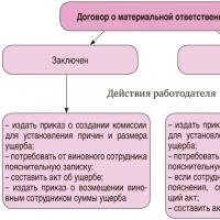 Overpaid wages: actions of the employee and the employer