We simplify life: we branch the trunk with the help of optical cross-countries. Installation of a high-density optical cross-section Instructions for the use of optical cross-sections
Good afternoon, BON optical crosses manufactured by NTC PIK look like this:


BON package:
Approximate configuration of BON in the figure:

Rules for installation and installation of BON:
1 After opening the package, check the external condition of the assembly units and parts of the optical box, as well as the availability of all accessories according to the delivery set.
2 Fasten the box to the wall using screws or anchor bolts from the delivery set, having previously marked the holes on the rear wall of the BOON.
3 Variant of preparation of the main cable for input into the BON.
3.1 Wipe the outer sheath of the optical cable with a rag over a length of 2.0 m. Perform cable cutting in accordance with Figure 1a.

3.2 At a distance of 1500 mm from the end on the cable sheath, make a circular incision Using a special tool on the entire marked length of the end of the cablemake a longitudinal incision, remove the shell. Remove the armor from the cable leaving 30 mm.
3.3 Take the wire PRPPM 1×2 250-300 mm long, release it at the end at a length of 60-70 mm from the insulation, tin it and put it with a bandage on the stripped and tinned section of the steel cable sheath (armor). Then solder the bandage with POSSU 30-2 solder. Over the wire bandage, on the entire section of the steel sheath, wrap two layers of insulating tape with 50% overlap.
3.4 Make circular and longitudinal cuts on the inner sheath of the cable. Make a longitudinal cut with a special tool. Next, remove the inner sheath from the cable core.
3.5 Wipe modules and CSE with a liquid to remove hydrophobic filling and dry rags.
3.6 If the optical cable has an armored cover of galvanized steel wires, cut in the following sequence in accordance with Figure 1b:
- make a circular cut with a utility knife outer shell optical cable at a distance of 1.5 m from the end of the optical cable, then a longitudinal notch of the optical cable sheath from the end of the optical cable to a circular notch;
- remove the outer sheath of the optical cable;
- unwind the coil of steel wires;
- cut off the excess length of the wires with side cutters or cable cutters;
- then perform actions in accordance with clause 4.3-4.3.5.
3.7 If there are water-blocking tapes and threads in the OK design, remove them flush with the edge of the inner shell. Remove hydrophobic filler,using a rag and D-Gel liquid.
3.8 If the OK design contains synthetic (aramid) threads, cut them at a distance of 150 mm from the edge of the outer sheath (see Figure 1a) with scissors for cutting synthetic threads, fasten the ends of the threads with an insulating tape.
3.9 Remove the cord fillers of the OK core (if any) with side cutters.
You may also be interested in: "How to choose the capacity of a linear cross when building a GPON network?".
4 Installation of cable BON.
4.1 Insert the end of the prepared optical cable through the special holes into the BON, cut the central power element to the required length, remove the plastic sheath (if any) and fix it with a bracket with two screws. If the optical cable has aramid threads, fasten them together with the central strength element, remove the excess length. To enter the cable into BON-72C, make a cross-shaped cut with a knife in the rubber plug. In BON-72SP, install a pipe at the cable entry point required diameter from the delivery set (the pipe must go outside, and the transport position of the pipe is installed inside the cabinet).
4.2 Fix the fiber-optic cable sheath with cable ties on the box body at the cable entry point. In BON-72S, a metal clamp is also provided for fixing the input cable. Ground the optical cable by connecting the shielding wire to the ground stud on the box wall.
4.3 Lay out the optical cable modules inside the OB. Determine the required length to the place of fixation in the cassette, remove the excess length of the optical module. Wipe optical modules and each optical fiber with isopropyl alcohol (2-propanol) and lint-free wipes.
4.4 Mark the modules with self-adhesive markers. The marking of the modules must correspond to the marking of the fibers of the optical holes.
4.5 Assemble the inserted optical modules into a bundle and fix the bundle with cable ties at the entrance to the splice cassette. Work should begin with the lower splice cassette.
4.6 Prepare the fiber to be assembled for splicing in accordance with the instructions supplied with the splicer. To remove the protective sheath of the optical fiber, use a stripper. Put on sleeves KDZS on the ends of the OF.
4.7 With the help of an optical fiber splicer, connect the optical mounting cords (pigtails and fibers of the cable being mounted. Follow the operating instructions for the splicer when working.
4.8 Check the integrity of the welded joint using a reflectometer.
4.9 Protect the place of the welded joint with the sleeve of the KDZS. It is forbidden to use the sleeve of the KDZS to protect more than one welded joint of the optical fiber!!!
4.10 After the sleeves have cooled down, install the welded joint in the seat of the splice cassette cradle. Lay out the stock of spliced optical fibers inside the splice cassette.
4.11 Lay the modules and pigtails inside the BON. Make sure that there is no tension on the fibers. Enter the necessary data on the plate for specifying the addresses of the crossing of fibers on the cover of the splice cassette.
Safety requirements:
When performing installation and installation work, one should be guided by the requirements of the "Rules for labor protection when working on linear structures of cable transmission lines" POT RO-45-009-2003.
When cutting the optical cable and its waste, use a special container. It is not allowed to get pieces of optical fiber on the assembly table, floor, clothing of installers, as this can lead to injury to unprotected skin during work and when cleaning the workplace.
In order to avoid damage to eyesight, it is forbidden to visually or with the use of optical instruments inspect the end of the optical connector, through which the optical signal is transmitted.
When working with optical connectors, precautions should be taken to prevent deformation, to prevent bending of the cable with a radius less than allowed by the specifications for the cable. The static bending radius of the cords during installation and operation must be at least 40 mm, for a multi-core optical cable - at least 20 cable diameters.
To prevent injuries, installers must be provided with personal protective equipment (goggles in accordance with GOST 12.4.013-85 and overalls).
8.1 The ODF is part of the PON site. ODF should have the following features:
− ensuring free access to any of the optical ports and the possibility of prompt execution of cross-connection work;
− increasing the cross-counter capacity during operation;
− ensuring the operational production of installation, installation and switching of the OF;
− a system for laying the OF and patch cords, which guarantees compliance with the requirements for the geometry of the OF bending;
− constructively support the installation of splitters directly in the ODF;
- take up minimal space.
The cross must comply with the "Technical requirements for high-density station optical crosses", approved by the Chief Technical Director of Kazakhtelecom JSC.
The basic principle of mounting a high-density ODF of a modular design is to cut the optical station and line cables (fibers) fed to the cross-connect into mounting modular tubes, through adapters shown in Figure 19.

Figure 19 Figure 20
Mounting modular tubes with 12 or 16 optical fibers are fed to the splicing and switching module shown in Figure 20, where the fibers are spliced into prefabricated picktails. Welded joints of fibers, reinforced with KDZS sleeves, are placed in cassettes. The design of the optical cross should provide for the extension of the splicing and switching module from the modular blocks to a length of up to 1.5 meters due to the stock of mounting modular tubes laid in the switching and splicing module of fibers, only when mounting (uncoupling) optical fibers of station and linear fiber optic cables. Connecting sockets of the SC/APC type are installed in special sockets of the patch panels.
8.2 Due to the large number of optical distribution systems of various designs, including the top or bottom feed of the FOC from cable growth or through a raised floor, a detailed description of the installation is not advisable, in each case, you should use the manufacturer's instructions. The length of the stock of fibers of the linear cable and picktails left on the cassette in the terminal device must be at least 0.5 m, and the stock of fiber optic cable left on the cable growth or in the raised floor should be at least 2 m. Placement options are shown in Appendix H.
NOTE For any design of the optical cross section, station cables or station patch cords must be fed to station splicing and switching modules installed in the upper part of the cabinet; installed at the bottom of the cabinet, it is necessary to feed the main linear FOCs. There are 2 options for mounting, (supplying) OLT line endings to an optical cross:
When installing the OLT in a shared room in the immediate vicinity of the ODF and the capacity of the GPON network node up to 2 thousand subscribers, the connection of the OLT outputs with the ODF trunk ports can be carried out directly using patch cords of the appropriate length;
When installing the OLT in a containment area and the capacity of the GPON network node exceeds 2 thousand subscribers, the connection of the OLT outputs with the station ports of the ODF should be carried out using 3-meter pigtails 48-96 terminated from the OLT side with station cables, and from the ODF side, the station cable should be inserted and unwired into station splicing and switching modules. In the latter version, the switching of the OLT outputs with any port of the line trunk cable should be carried out by short patch cords inside the ODF rack between the line and station ports of the optical cross.
8.3 Inside the premises of the PBX, up to the terminal cable equipment ODF, OC with a non-combustible sheath should be laid.
The fibers are charged into the splicer
Hello Habr readers! Everyone has heard about optical fibers and cables. There is no need to tell where and what optics are used for. Many of you come across it at work, someone develops backbone networks, someone works with optical multiplexers. However, I did not come across a story about optical cables, couplings, cross-connects, about the very technology of splicing optical fibers and cables. I am a splicer of optical fibers, and in this (my first) post I would like to tell and show you how it all happens, and I will often be distracted in my story by other things related to this. I will rely mainly on my own experience, so I fully admit that someone will say “this is not entirely correct”, “this is not canonical”.
There was a lot of material, so it became necessary to break the topic into parts.
In this first part, you will read about the device and cable cutting, about the optical instrument, about preparing the fibers for welding. In other parts, if the topic turns out to be of interest to you, I will talk about the methods and show on the video the process of splicing the optical fibers themselves, about the basics and some of the nuances of measurements on optics, touch on the topic of welding machines and reflectometers and others measuring instruments, I'll show you the splicer's workplaces (roofs, basements, attics, hatches and other fields with offices), I'll tell you a little about cable fastening, about wiring diagrams, about placing equipment in telecommunication racks and boxes. This will certainly come in handy for those who are going to become a splicer. All this I flavored with a large number of pictures (I apologize in advance for the paint-quality) and photographs.
Beware, lots of pictures and text.
Introduction
First, a few words about me and my work.I work as an optics splicer. He started as a telephonist and assembler, then worked in an emergency team servicing main optics. Now I work in an organization that takes general contracts for the construction of facilities and communication lines from various companies. A typical construction project is a cable line linking several containers of GSM base stations. Or, for example, several FTTB rings. Or something smaller - for example, laying a cable between two server rooms on different floors of the building and splicing at the ends of the cable crosses.
If the tender is won, suitable subcontractors are sought to perform the work (design and survey and construction and installation). In some regions these are our subsidiaries, in some regions we have our own equipment and resources, in others independent companies are hired. On our shoulders, control, elimination of jambs of subcontractors and various force majeure, all kinds of agreements with land owners and administrations, sometimes drawing up executive documentation for the constructed facility (documentation - mainly RD 45.156-2000, here is the list, plus more is added) section with different licenses) and so on. Often, work with optics is needed: to weld or digest an optical coupling or cross somewhere, to eliminate the consequences of a support knocked down by a street racer or a tree that fell on the cable, to carry out an input control of the cable drum, to take reflectograms of the site, and so on. These are the tasks I do. Well, along the way, when there are no tasks in optics - other tasks: from loading and assembling through courier and delivery to copying and paper work. :)
Optical cable, its types and insides
So what is an optical cable? Cables are different.
By design - from the simplest (shell, plastic tube-modules under it, the fibers themselves are in them) to super-sophisticated (many layers, two-level armor - for example, in submarine transoceanic cables).

At the place of use - for outdoor and indoor laying (the latter are rare and usually in high-class data centers, where everything must be perfectly correct and beautiful). According to the laying conditions - for suspension (with Kevlar or cable), for soil (with iron wire armor), for laying in cable ducts (with corrugated metal armor), underwater (complex, super-protective multilayer structure), for suspension on power transmission line supports (besides transmitting information, they act as a lightning protection cable). In my practice, most often there are cables for hanging on poles (with Kevlar) and for laying in the ground (with armor). Less often come across with a cable and with corrugated armor. It is also common to see a cable that is essentially a thin paired optical patch cord (yellow sheath for single mode and orange for multimode, a bit of Kevlar and one fiber; two sheaths are paired). Other optical cables (unprotected, underwater, for laying indoors) are exotic. Almost all cables I work with are designed like the picture below.

1 - central power element(in other words, a fiberglass rod, although there may also be a cable in a polyethylene sheath). Serves for centering tube-modules, giving rigidity to the entire cable. A cable is also often fixed behind it in a coupling / cross, clamping it under a screw. With a strong bend, the cable has a vile property to break, breaking along the way and modules with part of the fibers. More advanced cable designs contain this rod, dressed in a polyethylene sheath: then it is more difficult to break it and it will cause less damage to the cable when broken. The bar is also the same as in the figure, and very thin. The tip of such a rod is an excellent abrasive tool for fine work: for example, to clean the contacts of a relay or the area of a copper part to be soldered. If you burn it a couple of centimeters, you get a good soft brush. :)
2 -
themselves optical fibers(in the figure - in lacquer insulation). Those very thin filaments-optical guides, for the sake of which everything is started. The article will focus only on glass fibers, although plastic ones also exist somewhere in nature, but they are very exotic, they are not boiled by optics welding machines (only a mechanical connection) and are suitable only at very short distances and I personally have not come across them . Optical fibers come in singlemode and multimode, I've only seen singlemode as multimode is a less common technology, can only be used over short distances and in many cases is perfectly replaced by singlemode. The fiber consists of a glass “shell” made of glass with certain impurities (I won’t dwell on chemistry and crystallography, since I don’t know the topic). Without varnish, the fiber has a thickness of 125 microns (slightly thicker than a hair), and in the center of it there is a core with a diameter of 9 microns made of ultra-pure glass with a different composition and with a refractive index slightly different from the shell. It is in the core that radiation propagates (due to the effect of total reflection at the core-shell interface). Finally, on top of the 125-micrometer "shell" cylinder is covered with another shell - from a special varnish (transparent or colored - for color marking of fibers), which EMNIP is also two-layer. It protects the fiber from moderate damage (although without varnish, the fiber, although it bends, is bad and easy to break, the fiber will simply crumble from a mobile phone accidentally placed on it; and in varnish, you can safely wrap it around a pencil and pull quite hard - it will withstand). It happens that the cable span sags on some fibers: all the sheaths are torn (burnt, cut), Kevlar, the central bar burst, and some 16 or 32 125-micrometer glass fibers can hold the weight of the cable span and wind loads for weeks! However, even in varnish, the fibers can be easily damaged, so the most important thing in the work of a splicer is meticulousness and accuracy. One awkward move can spoil the results of a whole day of work or, if you are especially unlucky and there is no redundancy, you can drop the trunk connection for a long time (if, digging into the “combat” trunk coupling, you break the DWDM fiber under the spine at the cable exit).
There are many varieties of fibers: regular (SMF or simply SM), dispersion-shifted (DSF or simply DS), and non-zero dispersion-shifted (NZDSF, NZDS or NZ). Outwardly, they cannot be distinguished, the difference is in the chemical / crystalline composition and, possibly, in the geometry of the central core and in the smoothness of the boundary between it and the shell (unfortunately, I did not fully clarify this issue for myself). Dispersion in optical fibers is a harsh and difficult thing to understand, worthy of a separate article, so I will explain it more simply - it is possible to transmit a signal without distortion through dispersion-shifted fibers farther than through simple ones. In practice, splicers know two types: simple and “offset”. In a cable, the first module is often distinguished as a "bias", and the rest - for simple fibers. It is possible, but undesirable, to join a “biased” and a simple fiber, this causes one interesting effect, which I will talk about in another part, about measurements.
3 - plastic tube modules in which the fibers float in hydrophobicity.
Cable, cut to modules

They break easily (more precisely, they suddenly bend) when bent, like telescopic antennas in household receivers, breaking fibers inside themselves. Sometimes there is only one module (in the form of a thick tube), and there is a bundle of fibers in it, but in this case, too many different colors are needed to mark the fibers, so several modules are usually made, each of which has from 4 to 12 fibers. There is no single standard for colors and the number of modules / fibers, each manufacturer does it in its own way, displaying everything in the cable passport. The passport is attached to the cable drum and is usually stapled to the tree right inside the drum with a stapler.
Cable passport

A typical passport for a cable. I apologize for the quality.
However, there is hope that, say, the DPS cable from the manufacturers Transvok and Beltelekabel will still be the same in configuration. But you still need to look at the passport for the cable, where the detailed colors are always indicated and what type of fiber is in which modules. The minimum capacity of an “adult” cable that I have seen is 8 fibers, the maximum is 96. Usually 32, 48, 64. It happens that 1 or 2 modules are occupied from the entire cable, then black dummy plugs are inserted instead of the remaining modules (so that the overall parameters cables have not changed).
4 - film, braiding the modules. It plays secondary roles - damping, reducing friction inside the cable, additional protection against moisture, keeping the hydrophobe in the space between the modules and, possibly, something else. Often it is additionally tied with threads crosswise and moistened with a hydrophobic gel on both sides.
5 - thin inner shell from polyethylene. Additional moisture protection, protective layer between Kevlar/armor and modules. May be missing.
6 - Kevlar threads or armor. In the figure, armor is made of rectangular bars, but much more common of round wires (in imported cables - steel wires and difficult to cut even with cable cutters, in domestic ones - usually from nail iron). Armor can also be in the form of fiberglass rods, the same as the central element, but in practice I have not met with this. Kevlar is needed so that the cable can withstand a large breaking force and at the same time not be heavy. It is also often used instead of a cable where there should be no metal in the cable to avoid interference (for example, if the cable hangs along railway, where there is a contact wire with 27.5 kV nearby). Typical values of permissible tensile force for cable with Kevlar are 6...9 kilonewtons, which allows to withstand a large span under wind load. When cutting, Kevlar blunts the cutting tool terribly. :) Therefore, it is better to cut it either with special scissors with ceramic blades, or bite off with cable cutters, which is what I do.
As for armor, it is designed to protect an underground cable lying directly in the ground, without protection in the form of a plastic pipe, cable duct, etc. However, armor can only protect against a shovel, the excavator still tears any cables in the air. Therefore, the underground cable is laid in the ground for 1 m 20 cm, and above it at a depth of 60 cm a yellow or orange signal tape with the print “Caution! Don't dig! Below the cable”, as well as posts, warning signs and full houses are placed along the route. But still they dig and tear.
7 - external thick polyethylene sheath. It assumes the first all the hardships during the laying and operation of the cable. The polyethylene is soft, so it is easy to cut it if the cable is loosely tightened. It happens that when laying an underground cable, the contractor breaks this sheath several meters to the armor and does not notice it, moisture gets into the cable in the ground despite the hydrophobe, and then on delivery, when testing the outer sheath with a megohmmeter, the megohmmeter shows low resistance (high leakage current) . 
If a hanging cable touches a concrete pole or tree, the polyethylene can also quickly rub down to the fibers.
A polyethylene film and some hydrophobic gel may be present between the outer shell and the armor.
In Russia, unfortunately, optical fibers are no longer produced (here, alas, a joke about polymers would be appropriate). There is a Russian laboratory that makes experimental fibers for special purposes, as suggested by esvaf.
They are bought from companies such as Corning, OFS, Sumitomo, Fujikura, etc. But cables are made in Russia and Belarus! Moreover, in my practice, 95% of the cables that I have worked with are cables from Russia or Belarus. At the same time, imported fiber is laid in the cable. Offhand from my experience, I recall such cable manufacturers as Beltelekabel, MosKabel Fujikura (MKF), Eurocable, Transvok, Integra-cable, OFS Svyazstroy-1, Saransk-cable, Incab. There are others. Of the imported cables, only Siemens remained in my memory. Subjectively, all cables are similar in design and materials and do not differ much in quality.
Here, in fact, I talked about the device of optical cables. Go ahead.
Cable cutting: the necessary tool and technique
For cable cutting, as well as for welding, a number of specific tools are required. A typical set of a soldering assembler is a suitcase with NIM-25 tools, it contains all the necessary strippers, cable cutters, screwdrivers, side cutters, pliers, a breadboard knife and other tools, as well as a pump or vial for alcohol, a supply of hydrophobic solvent "D- Gel", non-woven lint-free wipes, electrical tape, self-adhesive numeral markers for cables and modules, and other consumables.
After completion consumables(screeds, worm clamps, etc.) and some auxiliary tools, it is quite enough to work with optics. There are also other sets, richer and poorer in terms of configuration (“NIM-E” and “NIM-K”). The weak point of most kits is the poor quality of the "aluminum type" case, which only looks nice, but actually consists of thin fiberboard covered with textured / corrugated foil, and riveted aluminum thin corners. It does not withstand long in field and urban conditions, and it has to be repaired and strengthened. In my case, the case withstood 3 years and, being all torn, pulled together with corners and bolts, with a “collective farm” organizer instead of the native one, was replaced with a regular plastic tool box. Some tools and materials from the standard set may be of poor quality. Some of the tools I personally did not need. Some have already been replaced in 3 years of work. As “branded” consumables are used up, some are replaced by “handy ones” without compromising the quality of work. So, the factory non-woven lint-free wipes for wiping fibers are easily replaced toilet paper Zev plus type. :) The main thing is that it should be unflavoured. Instead of expensive (about 800 r / liter) D-Gel, if you work outdoors, you can use AI-92 gasoline.
When cutting cables, it is important to maintain the length of the cable elements in accordance with the requirements of the instructions for the coupling: for example, in one case it may be necessary to leave a long power element to fix it in the coupling / cross, in the other case it is not required; in one case, a braid is woven from the Kevlar of the cable and clamped under the screw, in the other case, the Kevlar is cut off. It all depends on the specific coupling and the specific cable.
Consider cutting the most typical cable:
A) Before cutting a cable that has been in dampness for a long time or without a waterproofed end, you should cut off about a meter of cable with a hacksaw (if the margin allows), since prolonged exposure to moisture negatively affects the optical fiber (may become cloudy) and other elements of the cable. Kevlar threads in a cable are an excellent capillary that can “suck” water into itself for tens of meters, which is fraught with consequences if, for example, high voltage wires run parallel to the cable: currents can start to walk along wet Kevlar, water evaporates, crushes from the inside outer sheath, the cable bubbles and new moisture enters through the bubbles from the rain.
B) If there is a separate cable for suspension in the cable design (when the cable in cross section has the shape of the number “8”, where the cable is in the lower part, the cable is in the upper part), it is bitten out with cable cutters and cut off with a knife. When cutting the cable, it is important not to damage the cable.
C) An appropriate stripping knife is used to strip the outer sheath of the cable. NIM-25 is usually equipped with a Kabifix knife, as in the photo below, but you can also use a stripper knife for electrical cables, which is with a long handle. 
Such a stripping knife has a blade that rotates in all directions, which can be adjusted in length in accordance with the thickness of the outer sheath of the cable, and a clamping element for holding on the cable. Important: if you have to cut cables of different brands, then before cutting a new cable, you need to try a knife at the tip and, if it cuts too deep and damages the modules, the blade must be twisted shorter. There is nowhere worse than when the sleeve is already welded, and suddenly, when laying the fibers, one fiber suddenly “pops out” of the cable, because when cutting, the knife caught the module and broke this fiber: all the work was wasted.
With a stripper knife to remove the outer sheath of the cable, a circular cut is made on the cable, and then from it - two parallel cuts from opposite sides of the cable towards the end of the cable so that the outer sheath breaks into two halves. 
It is important to correctly set the length of the stripper blade, because if the blade is too short, the outer sheath will not easily split into two halves and will have to be torn off with pliers for a long time, and in the case of a long blade, you can damage the modules deep in the cable or blunt the rotating blade against the armor.
D) If the cable is self-supporting with Kevlar, then the Kevlar is cut off with cable cutters or scissors with special ceramic blades. 
trosobites
Kevlar should not be cut with a knife or simple scissors without ceramic blades, as Kevlar quickly dulls metal cutting tools. Depending on the design of the sleeve, it may be necessary to leave a certain length of Kevlar for fixation, this will be discussed in the installation instructions for the sleeve.
If the cable is intended for laying in a telephone duct and contains only a metal corrugation from the armor (so that rats do not gnaw through), it can be cut lengthwise with a special tool (reinforced plow knife). Or, carefully make a circular risk with a small pipe cutter or even an ordinary knife on the corrugation and, swaying , to achieve an increase in metal fatigue in the place of risk and the appearance of a crack, after which it is possible to remove part of the corrugation, bite the modules and pull off the corrugation. Such cutting should be carried out with particular care, since it is easy to damage the modules and fibers: the corrugation is not very strong, it can be washed in the place where it is picked with tools, and when pulled from the fibers, the sharp edges at the break point can cut through the modules and damage the fibers. Corrugated cable is not the most convenient for cutting.
If the cable is armored with round wires, they should be cut off with cable cutters in small batches, 2-4 wires each. Side cutters are longer and harder, especially if the wire is steel. Some couplings require a certain length of armor for fixation, and armor (including corrugated) often needs to be grounded.
E) For the thinner inner sheath found in some cables (e.g. self-supporting with Kevlar), a separate, pre-set stripper knife (maybe the same as for stripping the outer sheath of the cable) should be used so as not to interfere with the knife length settings every time you cut the cable. In this case, it is especially important to correctly set the blade length in the stripper knife, it will be less than in the stripper for removing the outer sheath of the cable, since the inner sheath is much thinner, and immediately below it are modules with fibers. With a certain skill, you can use an ordinary breadboard knife to remove the inner shell, making a longitudinal cut with it, but there is a significant risk of damaging the modules. You can also use a stripper to cut the coax.
E) Threads, plastic film and other auxiliary elements are removed from the modules using napkins and D-Gel / gasoline. The threads can be twisted one at a time, they can be torn off with a special sharp “plow” hook (may be included in the design of some stripper knives to remove the sheath). To remove the hydrophobe, a D-Gel solvent (colorless oily liquid, smells of orange, toxic) or gasoline is used. However, be careful with gasoline: office employees who have gasoline pouring at their side will not be happy with the aroma. Yes, it's a fire hazard.
Work should be done in disposable gloves (surgical, polyethylene or construction), since hydrophobe is a very unpleasant muck (the most unpleasant thing in the work of a jointer!), It is difficult to wash, after gasoline or hydrophobe, hands remain greasy for some time, and after cutting the cable, welding of fibers will be necessary, requiring clean hands and workplace. In winter, hands stained with hydrophobe are very cold. However, having got the hang of it, you can cut the cables almost without getting your hands dirty.
After removing the threads and separating the bundle of modules into separate modules, each module is wiped with napkins or rags with D-Gel solvent / gasoline, and then with alcohol until it is clean. Although, in order to save time and to get less dirty, you can proceed in the following way - initially cut the cable to the modules not to the end, but in the place where the cutting begins, by 30 centimeters, without wiping anything to bite the modules (see paragraph "e") and pull off the entire bundle of modules with winding and threads from the fibers, holding the clean end of the cable with your hand like a handle. Hands remain almost clean, time is saved. However, with this method of cutting, there is a risk of breaking some of the fibers or applying excessive tensile force to the fibers, which will adversely affect the attenuation of the fibers in the future, and it is also more likely to damage the modules, so this method is not recommended, especially in winter time when the hydrophobic aggregate thickens. First you need to learn how to do it right, and then try different optimizations.
g) At the required length, each module (except for dummy modules, they are bitten under the root, but first you need to make sure that there really are no fibers in them) is bitten with a stripper for modules (suitable for copper coax), after which the module can be pulled off without much effort with fibers. 
Biting the modules with a stripper is a very crucial moment. It is necessary to choose a notch of the exact diameter, because if the notch is larger than necessary, the module will not bite enough to easily remove it, if it is smaller, there is a risk of biting the fibers in the module. In addition, you should carefully monitor the stripper latch dog: if, at the moment of biting the module, it blocks the reverse motion of the stripper, fixing it in the “closed” state, then in order to separate the stripper and fold the latch, you will have to close the tool again on the already bitten module, while there is a high probability of biting the module, which will lead to the need to re-cut the cable. Remember that when biting one of the modules, other modules actively interfere with us, which must be held with the other hand, and the cable itself must also somehow be held in the air. Therefore, at first it will be very inconvenient and the cable should be cut together.
There are cable designs where the module is the only one and has the form of a rigid plastic tube in the center of the cable. For high-quality removal of such a module, it should be cut in a circle with a small pipe cutter (not included in NIM-25), and then carefully break in place of the circular risk.
When pulling modules, make sure that all fibers are intact and that no fiber is left sticking out of the pulled module.
If the temperature is low, the modules are thin, due to the design of the cable there is little hydrophobic (=lubricant) in the modules or the length of the removable modules is significant - the module may not be pulled off the fibers without effort. In this case, do not pull too hard, as stretching can affect the attenuation of the fibers at this point, even if the fibers do not break. You should bite and remove the module in 2-3 steps, in parts and slowly.
When cutting the cable, pay attention to the length of the fibers. It should be at least indicated in the instructions, usually 1.5-2 meters. In principle, you can cut and 15 cm and then even somehow weld, but then when laying the fibers in the cassette, there will be big problems: a large supply of fibers is needed just so that there is room for “manoeuvres” when laying, so that you can “ play" along the length and beautifully lay all the fibers in the cassette.
Sometimes it becomes necessary to weld into the transit cable without cutting it. In this case, just like a normal one, it is cut to modules, but the requirements for the care of cutting are tougher: after all, communication can already go through the cable. It is cut to modules and the modules are carefully inserted into the “oval” sleeve input (they won’t fit into a regular round one - they will break), for this input a special heat shrink kit and a metal clip with a hot glue block are used. This adhesive, when shrinking from heat, melts and fills the space between two cables, providing a tight seal. Further, the module into which it is necessary to weld is cut, those fibers from it that do not need to be soldered are welded back in transit, and those that we need are welded to the “tap” (branching) cable. Very rarely, a situation may arise when we need to take a fiber from a module, but we cannot cut the module (an important connection goes through it). Then apply kit for longitudinal cutting of modules: a “chamfer” is removed from the module longitudinally, the fibers are removed from it, wiped from the hydrophobe and sorted. Those that we need are cut and welded onto another cable according to the scheme, and the rest simply fit into the cassette. In this case, if a continuous cable is started, the length of the fibers should be twice as long (2-3 m), this is understandable.
The fibers must be clean (thoroughly wiped from the hydrophobe), special care should be taken that all the fibers are intact. Fibers require careful handling, because in the case when the cables are cut and wound up, welding is almost over and some fiber breaks at the exit from the cable, you will have to re-cut the cable and weld, which will take a lot of time and is extremely undesirable and unprofitable when the connection is quickly restored on an active highway. 
Optical fibers damaged as a result of careless cutting of the cable (the length of the stripper blade was incorrectly set to remove the inner sheath of the cable, as a result of which the modules were cut and some of the fibers were damaged)
G) The fibers should be rubbed well with lint-free wipes and alcohol to completely remove the hydrophobic filler. First, the fibers are wiped with a dry cloth, then with cloths soaked in isopropyl or ethyl alcohol. This order is named because a huge drop of hydrophobe remains on the first napkin (alcohol is not needed here), but on the 4-5th napkin you can already call on alcohol to help dissolve the remnants of the hydrophobe. The alcohol from the fibers quickly evaporates.
Used wipes (as well as scraps of cable sheath, chipped fibers and other debris) must be cleaned up after yourself - take pity on nature!
The purity of the fibers, especially towards the ends, has great importance for quality welding. Where there is work with microns, dirt and dust is unacceptable. The fibers should be inspected for the integrity of the varnish coating, the absence of dirt, broken parts of the fibers. If the varnish on some fiber is damaged, but has not yet broken, it is better not to risk it and re-cut the cable. Spend 10-15 minutes, otherwise you risk wasting a whole day.
H) Special adhesive heat shrinks are put on the cut cables, which are often included in the coupling kit (if the coupling has a branch pipe for cable entry). If the coupling provides for clamping the cable in raw rubber with sealant, then heat shrinkage is not needed. A very common and very unpleasant novice mistake is to forget to put on heat shrink! When the coupling is welded, the heat shrink is pushed over the coupling nozzle and shrinks gas burner, a blowtorch or an industrial hair dryer, providing a sealed cable entry into the sleeve and additional cable fixation. It is most practical to seat with a small burner, put on a can of tourist gas with a centrifugal clamp: one can is enough for dozens of welded couplings, it just ignites, unlike a blowtorch, it weighs little, there is no dependence on electricity, unlike an industrial hair dryer.
Before shrinking, the coupling pipe and the cable itself must be sanded with coarse sandpaper for better adhesive adhesion. If this is neglected, the following misunderstanding may turn out: 
If you still forgot to put on a heat shrink, a heat-shrink cuff with a lock (known as XAGA) will help. Collective farm sealing with electrical tape is impossible!
Some heat shrinks (for example, from Raychem) are covered with dots of green paint, which turns black when heated, indicating that this place no longer needs to be heated, but here it should be warmed up more. This is done because the heat shrink can burst if it is overheated in some place.
It is better to seat after the coupling is welded. If a trouble happens during welding (for example, a fiber breaks and you have to redistribute the cable), then you don’t have to pick a frozen thick adhesive heat shrink with a knife, and the heat shrink itself will not be wasted.
I) The cut cables are inserted into the coupling or cross, fixed, and the coupling or cross itself is fixed on the desktop. When fixing the cable in the sleeve or in the cross, you should be guided by the installation instructions - for different sleeves everything is different there. with trimming armor, winding sealant, etc.
So we brought the cut cable into the clutch / cross, now you need to measure and strip the fibers, put on the KDZS and cook according to the scheme. I will talk about this in the next part, since it turns out to be a bit much for one article.
Optical couplers
I'll tell you a little about optical couplings and crosses. I'll start with the clutches.An optical coupler is a plastic container into which cables are inserted and connected there. Previously, in the late 90s and early 2000s, when all specialized materials for optics were in short supply with exorbitant prices, some smart guys sculpted sewer fittings as couplings or plastic bottles. Sometimes it even worked for several years. :) Today, this is, of course, wildness, normal couplings can be bought in any medium and large city and prices start at 1500-2000 rubles. There are many clutch designs. The most massive and familiar design for me personally is like a series of Svyazstroydetal couplings "MTOK". There is a headband, from which branch pipes for cable entry protrude from the outside. A metal frame is attached to the inside of the headband, to which optical cassettes are attached. A cap is put on top (which for strength can be made with stiffeners), sealed with an elastic band. The cap is fixed with a detachable plastic clamp: the coupling can always be opened and closed without wasting a heat shrink repair kit. 
In general, Svyazstroydetal makes generally good couplings for various applications. Of the MTOK series, I personally like the L6 clutch the most: universal, inexpensive, easy to install. 
There are other couplings in the MTOK series - small-sized, for sewerage, for entering armored cables, for digging underground. For each coupling, it is possible to purchase additional accessories and kits for cable entry: for example, cast-iron armor protection of the MCHZ underground coupling, an extra set of optical cassette with consumables, or an additional kit for entering another cable.
If you need it cheaper, they have a series of "MOG" couplings, of which the most massive is the "MOG-U" coupling (Coupling Optical Urban, Shortened): at a price of less than 2000 rubles, we get a simple and high-quality coupling, which, by the way, some consider inconvenient for installation. 
Such a coupling will not look very good on a pole, and it is inconvenient to wind up a supply of cable with such a coupling while standing on a ladder, so they are usually placed in hatches. This clutch is designed to be placed in a telephone hatch on special standard consoles. The minus of the "mog" is that it does not have a locking detachable clamp and to open it you will have to cut off the heat shrink, and when closing it, use a repair kit from wide heat shrinks (if the cables are wound from one end) or a heat-shrinkable cuff (if the cables are on both sides). The MTOKs of the A series suffer from the same. In addition, if you enter cables from both sides, it is important not to forget to dress in advance plastic pipe on one of the “sides” of the cables, otherwise you can’t put it on without cutting it: beginners also suffer from this.
Also, sometimes there are couplings without nozzles, in which the cables are sealed by clamping in raw rubber or sealant. Here, for example, is the “SNR-A” coupling, which my partner and I welded as part of the construction of the FTTB ring. 
This method of sealing cables requires great care, since otherwise water may enter the sleeve, which is undesirable. First, the water in the sleeve can cause clouding of the glass of the fibers and damage to the varnish over time. Secondly, any metal will rust structural elements, the wire grounding the armor will rot, if any. Thirdly, Kevlar will draw water into itself. And most importantly, a clutch full of water will simply be crushed together with fibers in frost.
At least two cables are usually inserted into the optical box. Of course, you can come up with a wild wiring scheme, when one cable is inserted and welded onto itself, but usually 2-3 cables are inserted. If 4-5 cables are introduced, and even all the cables are different with different colors and different amount fibers in the modules, then the coupling turns out to be difficult for installation and subsequent analysis of what is soldered where. I cooked my first such clutch with a partner for 3 days! :) So it's better to design the network so that no more than 3 cables enter the clutch.
Optical crosses
The optical cross is designed to terminate the cable in the place where it was brought: at the base station, in the data center, in the data center, in the server room. A typical cross is a 19" metal box for mounting in a standard rack, a terminated cable is inserted into it at the back, and there are brackets with ports at the front.
Welded cross for 24 ports type FC / APC, one unit

Welded cross for 64 ports type LC, 2-unit

Working cross for 96 ports of FC type
There is also a cheaper option - when everything that is possible is thrown out of the cross, then it turns out something like this: 
Open cross for 8 ports of SC/APC type, 1 unit. The bad thing is that optical pigtails are not protected by anything and they can be broken by those who will dig in a box / rack, dragging, say, a new cable.
All these crosses are rack-mounted, but there are also wall-mounted options, and other rare ones. 
Wall cross for 16 FC type ports. By the way, it is poorly welded: the yellow pigtail shells do not go into the CDS and the fibers can break, and the fibers in the cassette are stacked with small bending radii
The cable inserted into the cross is welded with the so-called pigtails: in the photographs, these are thin yellow laces inside the crosses. Each fiber has its own pigtail. The other side of the pigtail contains an optical “plug” connector, which is inserted into the optical “socket” adapter from the inside of the cross. Outside the cross, switching is performed by optical patch cords (thick yellow cords). The patch cord differs from the pigtail by a stronger connector and the presence of Kevlar inside, so that if someone catches on the patch cord and pulls, it would be difficult to pull out. Well, patch cords have connectors on both sides, and pigtails have only one. If necessary, a temporary patch cord can be welded from two pigtails.
In principle, several cables can be brought into the cross, some of the fibers from them are welded together, and some are brought out to the ports. Then we get something that can be called a "cross coupling", while we save on materials and welding. This is sometimes done when installing FTTB, but it is undesirable to do this, as the complexity of the circuit increases.
Adapters and connectors
Optical cross-countries are characterized by the adapters used in them (more simply - optical sockets). They also exist a large number of standards and substandards.
In this picture - only a part of the "genera" and "types" of optical sockets
The standard is a complex of an adapter (socket) and a connector (plug). Of course, there are adapters between different standards, but these are crutches that are only suitable for measurements and which should be avoided in a constantly working communication line. The less all kinds of welded and especially mechanical joints in the line, the better. Of course, if the distance is small, the line will work, even if a couple of decibels are lost on some of the crosses. In the case of short lines, optical attenuators are sometimes specially installed. But for very long lines, where the equipment works at its limit, adding another cross or coupling (that is, some 0.05-0.1 dB of loss) can be fatal: the line will not rise.
The tip of the "fork" is, roughly speaking, a cylinder with a thin through hole under the fiber in the center. The end of this cylinder is not flat, but slightly convex. The tip consists of a wonderfully hard and scratch-resistant cermet, although metal ones are very rare. Rumor has it that people broke side cutters trying to bite through this tip. :) I myself easily scratched steel and glass with these tips. Nevertheless, they must be handled with care, do not allow dust to enter, do not touch the end of the connectors with your finger, and if you touch it, wipe it with a cloth soaked in alcohol. Ideally, a special microscope (optical or with a camera) is used to monitor the condition of the patch cords. Dirty - clean, scratched, if the scratch crosses the center with glued fiber - for write-off or polishing. Dirty and scratched sockets and patch cords - common cause attenuation in the line.
The optical fiber is fixed in the tip by gluing with epoxy (or some other) glue and then grinding on a special machine, although this is only done if you need to make long non-standard patch cords: it’s easier and cheaper to buy ready-made ones. The price of a conventional optical patch cord 2 meters long is about 200-400 rubles. 
Production of patch cords. emilink
In practice, standards such as FC, SC, LC are most often used. Less common are FC/APC, SC/APC, ST. LC is both duplex and single.
FC


Pros - great quality connections, therefore suitable for critical highways. Old proven standard. Metal (hard to break). If you move a well-screwed connector with your hand, this will not affect the connection.
Cons - unscrew / twist for a long time when switching. If they are closely located on the cross - it can be very inconvenient to crawl up to unscrew one of the connectors in the crowd of others.
The connector itself is fixed motionless thanks to the groove on it and the notch on the adapter, and only the knurled nut turns with your fingers.
SC


Everything is the same as in FC, only the adapter and connector are square, plastic and the connector is fixed by snapping, not screwing. Pros - cheaper than FC, more convenient and faster to switch, cons - plastic is easier to break, less connection-disconnection resource. Sometimes it happens that the amount of reflection and attenuation on the connection changes noticeably after touching the connected connector, which is undesirable for critical lines. The color of the connectors is usually blue.
LC and LC Duplex


They are similar in properties to SC, but have much smaller dimensions: a two-unit cross on LC accommodates as many as 64 ports, and on SC - only 32. Due to their small dimensions, they are often mounted directly on optical multiplexer boards.
FC/APC, SC/APC, LC/APC
Same as FC, SC and LC, but with an oblique (A - angle) tip polish.
Difference between regular and oblique polished ceramic tips. The image is a little inaccurate: in fact, in the case of both polishing, the ends are not flat, but slightly convex, respectively, when connected, only the centers of the tips, where the fiber is, will touch.
Such adapters and connectors are made in green and when compared with the usual UPC (or simply PC) polishing, the difference is visible to the eye. This is necessary to reduce back reflection at the junction of two connectors. As far as I know, this type of polishing was developed for transmitting analog television over optics so that there was no ghosting of the image on the screen, but I could be wrong.
It is possible to join “ordinary” and “oblique” polishing, but only if it is necessary to take a reflectogram according to the principle “if only the length of the path can be seen”: a large air gap will give strong losses and strong back reflection.
For today, my story is over. Ask questions, I'll try to answer. If you find this topic interesting - I will write a sequel.
A fiber-optic network for several premises (buildings) is usually a connection of several lines into a common backbone, which is then sent to a switching node with a single multi-module cable. This branching of the highway into several lines can be carried out in a variety of ways, depending on the conditions and technical means, but most simple option there will be a use of a special optical cross for connecting a multi-fiber cable to a single-channel optical cord.
To begin with, it is necessary to clarify what actually is an optical cross. V general sense this is a box designed to protect the connection of optical fibers, including organizational and connecting elements. However, unlike, which also serve to protect the junction, crosses have sockets in their configuration, to which optical fibers of the main cable are connected through special devices - optical pitgalls. It is through these sockets that single-channel lines terminated with the appropriate connector on a conventional optical patch cord are connected to the trunk.
Network installation using cross boxes
This is the most convenient solution when you run a single trunk along the building, branching fiber modules from it as you pass the premises. The same situation usually develops if a powerful fiber-optic backbone runs along the street and releases branches to the houses. If in the case of internal network wiring you need wall-mounted indoor cross-countries with patch cord sockets, then to connect the lines to the street main, you need to select a box depending on the characteristics of the cable of this line and specifications installation. For serial diversion of lines from a common trunk, cross-countries are suitable, equipped with an input and output channel for the trunk cable and sockets according to the number of lines planned for connection at a given point. Most often, one outlet is enough. In the event that the breeding of a single highway occurs immediately from one point, then there is only one entrance for the main cable, but there can be quite a few sockets. Most often, this method of dilution of the line is carried out in switching nodes and technical rooms. For ease of installation of cross-connects in such cases, they are also made in the RAC version for placement in switching cabinets. In addition, optical distribution boxes can be made with the possibility of subsequent opening without complete dismantling of the connection and without it. Thus, in order to select the most suitable optical distribution box, you need to know:
.connection type (transit branch of one, several communication lines or terminal branch);
.technological conditions (outdoor or internal installation, wall or RAC version, the maximum possible dimensions and weight, the possibility of opening without dismantling);
.type of connectors to be connected (for exact matching with sockets).
It will be useful to know the type of both the main cable and the cable of the connected lines.
Installation of an optical cross
Actually, the installation of the cross box itself is quite simple. The main cable is inserted into the opening of the box intended for this purpose, the sheaths are removed and the cable is divided into modules. The withdrawn module is dissected, the fibers are stripped and prepared for connection with pitgalls. Pitgale is a connector with a small section of optical fiber that connects to the inside of the cross-country outlet. The connection to the end of the pitgale fiber is most often made by welding, but you can also glue it and use splices - many optical crosses contain splice cassettes. The cable stock is placed inside the cross box without sharp bends and twists, usually there are special brackets to fix the cable inside the case. The sleeves (or splices) of the connected fibers are placed in the organizer cassettes, the pitgalls are connected and the installation is completed, sealing the inlet and outlet holes of the cable and closing the cross box.
To enter the optical cable and connect the station equipment to the line, optical crosses are used. To implement the FOCL construction project, it is necessary to select the brand and capacity of the optical cross. For the terminal points of the designed FOCL at Zhetygen station and Korgas station, the required number of outlets in the cross is 16. At intermediate points, Kurozek station and Shelek station, where two cables are laid, 32 outlets are needed. Such requirements are met by optical cross-countries of the type PR-16 manufactured by OAO 2ASistem, Tula. At the end points, one cross is installed, at the intermediate points, two (sides A and B), in total, 6 optical crosses are required.
Since optical pigtails are ordered separately, we will choose standard 1m long pigtails. with FS-type connectors (respectively, the optical distribution box will also be equipped with FS-type connectors).
Optical cross (Fiber Cross) Distribution panel PR 16
General information.
Optical cross (Fiber Cross) distribution panel PR 16 provides:
- - Input, placement, fastening and storage of stocks of station and linear cables;
- - Termination, connection, switching of linear and station cables with optical fibers in a public communication network, in technological communication networks and special-purpose communication networks;
- - Connection of control and measuring equipment;
- - Possibility of marking linear and station chains.
Technical characteristics of the optical cross.
The maximum number of incoming linear fiber-optic cables is 4 pcs.
The maximum number of optical connecting sockets on the panel is 16 pcs.
Dimensions Optical Cross (Fiber Cross) PR 16 - 484 x 280 x 44mm
The mass of the Optical Cross (Fiber Cross) of the distribution panel PR 16 - 2.4 kg.
Type of optical ports - FC, SC, ST, FC/APC, SC/APC
Delivery set of optical cross.
Optical cross (Fiber Cross) distribution panel PR 16 is completed according to table 3.3
Table 3.3 - Delivery set of optical cross
|
Name |
Quantity, pcs. |
|
|
Distribution panel |
||
|
Splice plate |
||
|
Screw-washer-nut kit |
1 (delivered by agreement) |
|
|
Screed 80mm |
||
|
Screed 140mm |
||
|
Platforms-organizers |
||
|
By number of ports |
||
|
Passport products |
Notes.
It is allowed to replace the products included in the delivery set with similar others that do not impair the presentation, performance characteristics and comply with safety requirements.
Supplied as agreed with the customer
Safety requirements for optical distribution.
Before starting work, carefully study this passport.
The optical cross must be used in accordance with the purpose indicated in the passport.
Optical cross device (Fiber Cross) PR 16.
The optical distribution box is a metal box painted using powder coating technology, which provides reliable protection against external influences. Inside the optical cross there is a splice cassette (splice plate) for stacking sleeves and a supply of fibers (it is possible to place 24 fibers on one splice cassette)
The optical cross has four holes for the input-output of the optical cable. The holes are closed with rubber plugs to protect the internal space of the optical cross from dust; when installing an optical cable (OK) in PR 16, you can choose one of the four holes for entering OK (or use all four if necessary).
Installation instructions for optical cross (Fiber Cross) PR 16
Removing the packaging - be careful not to damage the optical cross with the tool. After opening the package, check the external condition of the assembly units and parts of the optical distribution box, as well as the availability of all accessories according to the packing list.
Preparing for installation
Before proceeding with the installation of OK, make sure that the mounting brackets on the right and left on the sides of the optical cross are rigidly fixed;
Place the Optical cross (Fiber Cross) PR 16 on the desktop for mounting OK.
Figure 3.10 - General form distribution panel Fiber Cross PR 16 (in the photo without the top cover with FC connectors).
Cutting and cable entry
Cut the cable according to Figure 6.14.
Enter the cable into the Optical cross (Fiber Cross) PR 16 through the hole, cutting the rubber membrane.
Fasten the OK using the ties included in the kit. Fasten the central strength element with the bracket and screws as shown in figure 3.12.
Slide the heat shrink sleeves onto the pigtails.

Figure 3.12 - Optical cable entry
Optical fiber work.
Strip the fibers and weld in accordance with the recommendations for the welding equipment used;
Number the modules of the installed cable;
Number the pigtails and weld them with the appropriate fibers;
Bake the heat shrink sleeves (heat shrink sleeves are included);
Place the sleeves and fiber supplies in the cassette according to Figure 3.14, 3.15. (drawings of input of cable modules and laying of pigtails are separated for readability).
When laying stocks of cable fibers, sleeves and pigtails, make sure that the bending radius of the fibers and pigtails does not exceed 30 mm
Close the splice cassette with a transparent cover.
Connect the pigtails to the adapters according to their numbers.

Figure 3.13 - Insertion of cable modules

Figure 3.14 - Scheme of laying pigtails
Rack mounting.
Optical cross (Fiber Cross) distribution panel PR 16 is fixed in a 19 inch rack with four screws M 6 (fixing screws are not included in the delivery set). Lay and fix the cable stock in convenient location.
To assess the quality of the installation of the optical cross-section, reflectograms of each optical fiber are taken in the regeneration section. With normal optical attenuation and no defects on the welded joints, the station equipment is connected to the line using patch cords.
Table 3.4 - Organization of jumpers on the optical cross of the Kurozek station access node

At all communication points on optical crosses, 1-4 OBs are switched to Huawei OptiX OSN 1500B equipment. A linear path is organized for 1-2 OBs for the operation of a digital transmission system, 3-4 OBs are also connected to digital equipment and are used for automatic redundancy of the linear path.
 Flexible removable dentures: design, features and benefits Varieties of soft dentures with photos
 Normal weight gain of a newborn during the year
 Norm of alcohol consumption
 What to do with alcohol poisoning at home
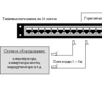 Where are the boundaries between these categories of consumers?
 What is an asset directory
 Free programs for Windows free download