Mixing unit for heated floors: rules for installing a distribution manifold
Water heated floors are a little more difficult to regulate than their electric counterparts. Regulatory functions are performed by two important devices - a mixing unit for heated floors and a collector that uniformly supplies water to all circuits of the system. Using them, you can obtain the optimal temperature of the coolant, as well as its quantity, i.e. make the heating equipment operate as efficiently as possible.
This unit is also called the mixing module, which fully corresponds to its purpose. This device is designed to mix water coming from a heating boiler with the same water, but from the return branch of the circuit, in order to obtain a coolant with an acceptable temperature.
The boiler usually heats the water quite strongly, up to 80-90 degrees. For underfloor heating systems, this temperature is quite high, so the coolant needs to be diluted, and the easiest way to do this is with a return flow that has already cooled down.
Such devices install heating systems with two or more working rings, if underfloor heating is an additional method of heating simultaneously with radiators, and when the house is heated only with underfloor heating.
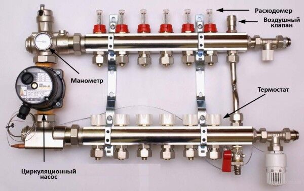
The mixing unit for organizing a heated floor with liquid coolant includes a number of temperature sensors and a control head, which allows you to supply coolant with the desired temperature to the circuit
The main components of the mixing unit are two-way valves with thermostats, a three- or four-way valve and a circulation pump. If the boiler is already equipped with such a pump, then for the heated floor you will have to purchase another device; it will work separately. The coolant is usually supplied to radiators at a temperature of 70-90 degrees, but for heated floors it will have to be cooled to 35-40 degrees.
This is how the process of mixing cooled return flow is carried out in a system with a three-way valve:
- Hot water is supplied from the boiler.
- The coolant passes through a three-way valve and enters the circuit leading to the underfloor heating manifold.
- The temperature sensor records the temperature of the liquid.
- When the temperature is above normal, the three-way valve is activated.
- It opens and the coolant begins mixing with the flow of cooled liquid from the return.
- When the coolant temperature drops to a predetermined level, the valve closes.
A two-way valve shuts off the flow of a new portion of coolant into the circuit until the water circulating through it cools to the required temperature.
Four-way fittings for heated floors are divided into two types: X-shaped, operating on the principle of two-way valves, and rotary, allowing mixing of the hot coolant with the return flow in impeccably precise proportions.
In addition to the pump and valve, to install and use the mixing unit, you will need a temperature sensor, as well as a thermostat that will turn off the pump if the water temperature is excessively high. Often the mixing unit is sold together with the manifold, but if it is not included in the kit, you will have to purchase and install the necessary elements correctly.
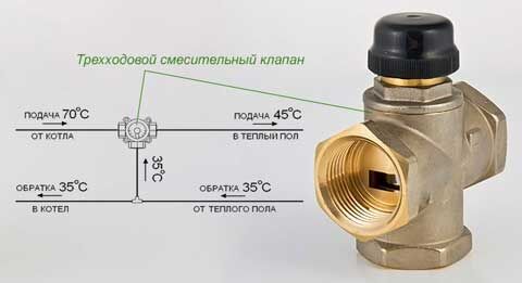
The three-way mixing device for water heated floors is designed in such a way as to control the temperature of the coolant by mixing cold and hot water flows
In this case, the following order should be observed: first install the three-way valve, then the circulation pump, after which the manifold is connected. With this scheme, the pump will supply coolant through the valve. If you place a pump in front of the valve, the latter simply will not work, since the flow will simply be directed incorrectly.
It is necessary to install a check valve on the pipe through which the cooled coolant flows so that cold water does not flow back into the system. Another useful element that will ensure normal operation of the mixing unit in systems with a two-way valve is a bypass. If all the holes on the collector are closed, the coolant will flow into the system through the bypass and will circulate along a closed path until it cools down.
In heating systems with two-way shut-off and control valves, a bypass is a mandatory element. In systems with three- and four-way valves, you can easily do without it. True, coupled with a three-way bypass valve allows you to regulate both quantitative and qualitative indicators of the coolant.
In addition to the bypass, a balancing valve must be included in the circuit with a two-way valve, with the help of which the volume of coolant flowing through the bypass is regulated. This device is needed to control the portions of cooled water mixed into the hot coolant.
A set of devices, called a mixing unit, can be purchased in the store as a ready-made kit. But, according to reviews from experienced craftsmen, buying individual units will be more reliable and will cost less. Systems with two-way valves and thermostats are suitable for compact circuits with small boilers. When choosing a three- or four-way valve, you should take into account its performance and the size of the area served by the system.
In small areas, a device that passes about 2 cubic meters will be sufficient. m of coolant per hour. But if we are talking about an area over 50 sq. m, it is better to take a mixing tap with a capacity of 4 cubic meters per hour. There is an adjustment cap on top of it; you can use it to set the temperature of the coolant.
Adjustment is not always necessary, since the manufacturer usually sets this indicator at an acceptable level. High-performance models of three-way valves come not only with caps, but also with servo actuators. But when connecting the mixing unit, you must take into account the features of the radiator heating system.
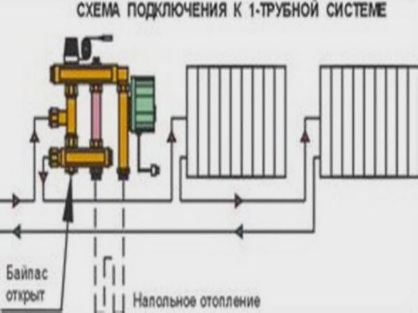
When connecting a water heated floor mixing unit simultaneously with a single-pipe radiator heating system, the bypass should always be left in the open position
Bypass is a necessary element when installing a mixing unit. Experts recommend installing a bypass valve on it. This is necessary so that if excessive pressure occurs in the system, part of the coolant is redirected to the return.
An important condition for a one-pipe heating system is that the bypass must remain open so that the circuit receives a constant flow of coolant. But when connecting to a two-pipe system, the bypass should be closed. If a water floor serves as the main method of heating, then, if desired, you can do without installing a mixing unit altogether.
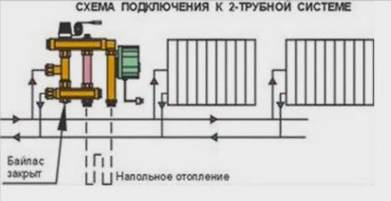
If a water heated floor is installed as auxiliary heating with a two-pipe radiator system, then the bypass must be closed
In this case, the function of regulating the temperature of the water entering the circuit is performed by a thermostat. In this case, the coolant, heated to 70-90 degrees, will immediately enter the heated floor system. As soon as this hot flow reaches the return of the collector, a thermal relay installed in this place detects the increased temperature and stops the circulation of the coolant.
When the water cools to a predetermined temperature, for example, to 40 degrees, the thermostat is activated and circulation resumes. This option has a significant drawback - not every floor covering easily tolerates heating up to 80 degrees.
This heating mode cannot be used for either parquet or linoleum, but for ceramic tiles this is a completely acceptable option. Another case when a mixing unit is not necessary is when the coolant is heated by a heat pump, since the water temperature is unlikely to be above 40 degrees.
Purpose of using the collector
A collector is a device with which the coolant flow is distributed over individual circuits of the water floor and then returned back for heating. The collector unit looks like two pipes with holes to which the system circuits are connected.
The presence of a distribution manifold in the heated floor arrangement makes it possible to control the volume of coolant flow. One of the collector pipes is the supply pipe; hot water flows to it and the inputs of the water floor circuits are connected to it. The return circuits are connected to the return pipe of the collector. The openings to which this connection is made are usually equipped with threaded, fitting or other connections.
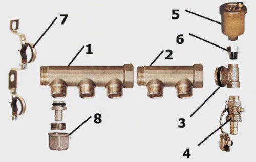
The collector consists of a number of elements such as the collector itself (1 and 2), an adapter for the Mayevsky tap (3); drain valve (4); air vent (5); valve (6); bracket (7); Eurocone (8)
Various devices are also installed here with which you can regulate the coolant flow rates. The simplest version of an industrial manifold is a pipe with a connector called a Eurocone. This is a completely convenient and reliable unit, but it does not allow you to control the flow of water. To effectively use such a device, you will have to additionally purchase and install a number of elements.
The manifold made in the DPRK is a little more complicated. In addition to the connections at the outlets, valves are installed here; no automatic means of regulating the flow are provided. This is an excellent and inexpensive option for a water floor in a small area with two or three contours of the same length.
Such a system does not require complex management. But on large areas, this type of collector will have to be supplemented with automation. In addition, the center-to-center distance between the feed and return sections of Chinese devices does not meet the standards adopted in Europe, which can cause problems when connecting it to European-made devices.
Ball valves in such devices are sensitive to low-quality water, and over time they begin to leak. To fix the problem, it is enough to replace the O-rings, but you must take into account the fact that the need for such repairs will arise periodically.
If the operation of the water floor system is intended to be automated, it makes sense to purchase at least a manifold with control valves. Servomotors can be installed on such valves, connected to thermostats in the rooms. This will ensure automatic control of the coolant flow in accordance with data on the air temperature in a particular room.
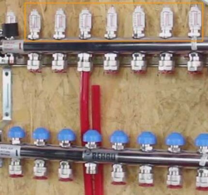
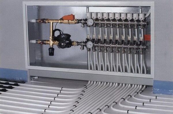
To automate the operation of a water heated floor system, flow meters are installed on the collector supply (indicated by a frame), and connectors for servo drives are installed on the return (blue caps at the bottom)
It is most difficult to control a water floor system in which the individual circuits vary markedly in length, but in complex systems this is usually the case. In such a situation, the optimal choice would be a manifold with flow meters installed on the supply side, and sockets intended for mounting servos on the return side.
Using flow meters, it will be possible to adjust the intensity of the coolant flow, and servo drives in conjunction with thermostats allow you to set the appropriate temperature on each circuit. If there is no need for automatic control, you can purchase a supply manifold with flow meters, and a return manifold with conventional valve taps.
It happens that it is not possible to choose a collector with the number of connection sockets that corresponds to the project. Then you can take the device “with a reserve”. And the extra holes are simply closed with plugs. This solution may be useful if you later need to add a couple more loops to the water floor system.
Water floor in a multi-storey building
It is believed that the construction of a water floor system in high-rise buildings is impossible, but this is not entirely true. In practice, such a project can be implemented, but requires agreement with the central heating service provider. They can be installed exclusively on the first floors of buildings. Two options are used here: completely replacing the radiator system with a water floor or installing an additional heating system along with the operation of radiators.
The optimal location for connecting a water heated floor system in an apartment building is the place where the return of the common riser is connected to the main line that discharges the coolant to the boiler room
In the first case, it is necessary to carefully calculate the coolant flow in the new system, since it must correspond to the previous volumes. It is not necessary to reconstruct all the heating in the apartment; you can limit yourself to just one room. If the water floor plays the role of auxiliary heating, heat meters will be needed. In addition, it is necessary to clarify whether a centralized heating system can cover the increased power and coolant consumption.
If a high-rise building has a radiator system with overhead wiring, then it is best to connect the water floor at the junction of the return of the common riser with the main line leading to the boiler room. Filters must be installed in front of the water floor. This is necessary, given the low quality of the coolant in domestic centralized systems, otherwise the heated floor circuit will very soon become clogged.
Filters should be cleaned regularly. They are more than relevant when directly connected to a central heating system, but the use of a heat exchanger helps make the problem of blockages less acute and the operation of the water floor more stable. But you will need to install an expansion tank, a heat exchanger, a safety group and a filter.
Features of collector installation
When installing a water floor collector, the supply part of the device must be placed higher than the return. You can do the opposite, but such a rearrangement does not make much sense. The collector will work, just with the upper return part of the heat from the supply part will be transferred to the reverse flow, i.e. thermal energy is simply lost.
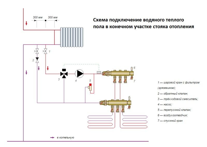
When assembling and installing a water floor collector assembly, it is extremely important to connect all the elements of this device in the correct order, for example, using this diagram
An important point is the installation of flow meters. They should be installed specifically on the supply part; on the “return” side these elements are useless. In addition to collectors, flow meters and servos with temperature sensors, for installation you will need a drain valve, as well as a Mayevsky valve with an adapter, connecting elements for water floor pipes, a shut-off valve, etc.
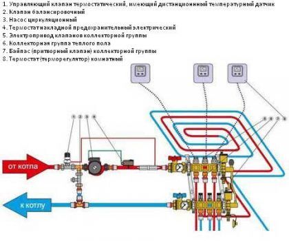
Unlike heating collectors, when installing a water heated floor, flow meters are always installed on the supply side, and servo drives with thermostats are installed on the return line
A manifold cabinet is designed to install all these devices. This is a metal box with doors, inside there are adjustable guides. This device greatly facilitates installation, but is not cheap. Therefore, if there is a niche of suitable size in the area of the installation site, you can use it.
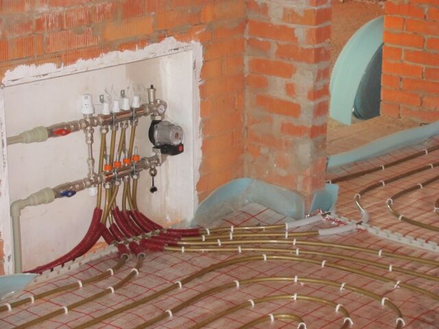
If the collector is mounted without a special cabinet, it must be suspended on brackets. As for the installation location of the collector, the rule applies in this regard: the higher, the better, i.e. It is best to install the collector at the highest point of the system.
The manifold cabinet is a very convenient device that facilitates the installation of a water heated floor system. But if you want to save money, it can be replaced with a niche in the wall
This is due to the need to remove trapped air from the system, for which a Mayevsky valve is installed at the top point of the collector. In addition, it is best to install the collector at an equal distance from all rooms, i.e. closer to the center of the system so that the lengths of individual circuits vary minimally.
Typically, only nine separate underfloor heating rings can be connected to one manifold. If the heating system is too complex and more than nine circuits need to be installed, two or more collectors will be needed. In a multi-story building, it is not always possible to install a collector at the top. Then you can place it lower, even in the basement. But the problem of removing excess air from the system will have to be solved differently.
The Mayevsky tap on the collector itself will be useless. An air vent device together with a shut-off valve installed in front of it will have to be installed on the return line of each circuit. Installation is carried out in the area between the pipe and the collector; free access should be provided to the Mayevsky tap.
Thus, if the collector is installed too low, instead of one Mayevsky tap, as many air vents will be needed as the number of circuits will be laid. Plus the same number of shut-off valves.
The collector is installed according to the following scheme:
- Installing a collector cabinet or preparing a special niche.
- Assembling the manifold, installing additional modules: servos, flow meters, etc.
- Connection of the manifold supply to the pipe leading from the boiler.
- Installation of a shut-off valve on the collector return.
- Installation of the collector in a cabinet/niche.
- Connecting pipes to the supply and return parts.
- Installation of the mixing unit.
- Checking the quality of installation, eliminating deficiencies.
Typically, the installation of the collector begins even before laying the pipes and pouring the screed, so you need to take into account that upon completion of the work the floor level will rise noticeably. The manifold cabinet already takes this point into account. But when installation is carried out using brackets, the device should be placed approximately one meter from the subfloor.
Do not install the water heated floor collector too low; lack of space can create problems when connecting pipes to the connectors
Do not hang the collector too low; this position may complicate the process of connecting pipes. The connection to the polypropylene pipes leading from the boiler is made using a connector on which there is a nut for the manifold thread and a coupling for polypropylene pipes.
The air vent must be installed at the top of the manifold, and its head will be directed upward. But the heads of elements such as flow meters and servos will point down when installed correctly. Typically the thread on the manifold is three-quarters of an inch, but Mayevsky valves have a half-inch thread, so you need to use an adapter. The adapter material must match the manifold material.
There are two threads on the return pipe of the manifold, one of them is needed for connection to the heating boiler, and the second is for installing a shut-off valve. All threaded connections require sealing, which can be achieved using an O-ring or, if such a ring is missing, by winding tow, linen thread, FUM tape, etc.
When assembling a mixing unit for a water heated floor, all threaded connections should be carefully sealed using FUM tape or other materials
When connecting a metal-plastic pipe to the manifold connector, the edge of the pipe must be flared and cleaned. This measure will protect the seals from accidental damage. After this, put a union nut on the pipe, then a crimp washer, carefully attach the pipe to the connector, tighten the nut by hand, and then carefully tighten it with an adjustable wrench.
A mixing unit should be installed before or after the collector. If the installation of this unit is not intended for some reason, a bypass with a shut-off valve is installed instead. The mixing unit is usually secured using union nuts. Such elements require the mandatory use of rubber gaskets.
Making a homemade collector
To make a manifold from polypropylene pipes, it is recommended to use structures with a diameter of 32 mm or 25 mm, corresponding tees and shut-off valves. How many underfloor heating loops will be connected, how many tees and valves will be needed for the manifold. You will also need to purchase a circulation pump and valve for the mixing unit.
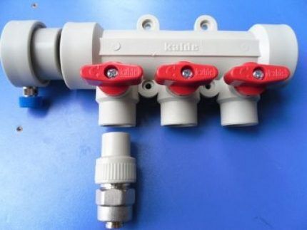
If the water heated floor system does not need serious automatic regulation, you can make the collector yourself or purchase a simple model with conventional shut-off valves
To solder pipes, you need a special soldering iron, as well as at least minimal experience in using such equipment. The supply and discharge sections of the collector are formed from tees and pipes. The pipe sections must be very short so that the tees are separated by very little space.
After this, stop valves are soldered, as well as fittings for connecting to the pump, etc. Such a simple device will not be expensive if you do not install flow meters and other control elements. But a more advanced plastic collector is easier to buy than to make; the cost of such a device is low.
Video on underfloor heating collectors
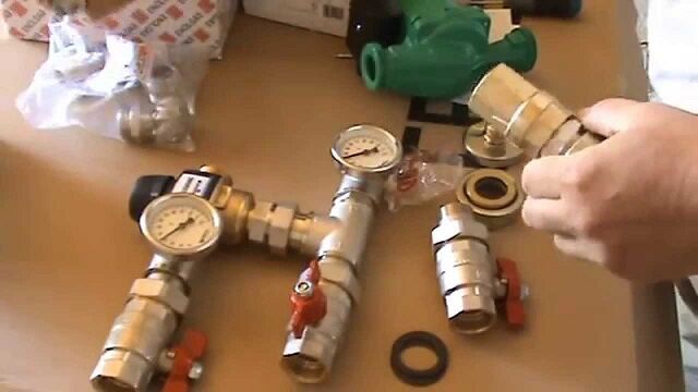
Interesting material on assembling and installing the mixing unit:
The video demonstrates the process of assembling a set of manifold elements:
How to make an inexpensive collector yourself is described in this video:
Distribution and mixing units are very important elements for a water floor. You can do without them only if the system includes only one or two circuits and occupies a small area. But if the decision is made to create a high-quality water floor, then all these components must be assembled and installed correctly so that the system works with maximum efficiency and minimum costs.
 Masonry mortars for brick kilns
 Why do the windows in the apartment fog up?
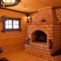 Construction and diagrams of brick stoves
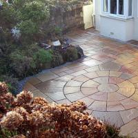 How to lay paving slabs: tips and tricks
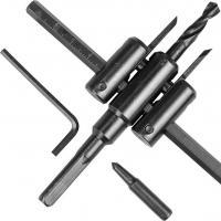 How to drill tiles in the bathroom
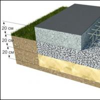 Monolithic slab on coarse soil
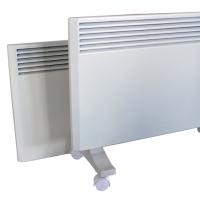 Which electric heater is economical?