Wastewater treatment plants. Sludge sites of treatment facilities Sludge sites of treatment facilities Scheme
Sludge sites of treatment facilities are necessary for sludge dewatering Wastewater.
The foundation of these sites can be both with a natural foundation (with and without drainage), as well as with surface drainage. Silt pads are planned plots of land (maps), which are surrounded on all sides by earthen ridges.
Sludge from settling tanks or digesters, the moisture content of which is from 90 to 99.5%, is poured into areas with a certain frequency and dried to 75-80%. A small part of the sediment seeps into the ground, but a larger percentage of it evaporates. Natural bed sludge beds do not provide drainage if they are placed on soil with good filtration capacity. And for dense, poorly permeable soil, tubular drainage is created, laid in ditches with crushed stone and gravel.
Treatment facilities of small sizes have a width of 10 m, and for large ones it increases to 35-40 m. The pits are separated by protective rollers, with a height of 0.3 m above the working level. Sediment is distributed over the maps using pipes. Sludge beds are promptly freed from sediment. At large sewage treatment plants, the sludge is removed using bulldozers and scrapers. For treatment facilities with a capacity of more than 10,000 m3/day, sludge platforms are arranged with settling and surface drainage of sludge water. As it accumulates, the upper layer of interstitial water is pumped into primary settling tanks. Subsequent dehydration of the sludge occurs due to the evaporation of moisture from the surface.
The area of sludge beds depends on the volume of sediment, the type of soil on which they will be organized, climatic conditions and the consistency of the sediment. Natural drying can be accelerated by agitating the sediment. During this process, the vegetative layer is removed and the surface crust is destroyed, which accelerates the drying of the sediment in the warm dry season and contributes to deeper freezing in the winter. Sites of the natural cycle depend on climatic conditions, which is important in the creation of the project and the subsequent operation of such sites.
GC "Poleka" is engaged in the design, installation and subsequent maintenance of treatment facilities, including the maintenance of sludge sites. We offer our customers turnkey services and provide quality assurance for equipment with a service life of up to 50 years. The use of modern and time-tested technologies makes it possible to create reliable and easy-to-use treatment facilities.
→ Wastewater treatment
Silt pads and silt ponds
Sludge beds are one of the first sewage sludge treatment facilities. Sludge beds are designed for natural dehydration of sludge generated at biological wastewater treatment plants. However, even in the era of intensive introduction of mechanical sludge dewatering facilities, sludge beds are the most common method of sludge dewatering in Russia. Currently, 90% of all sludge generated in Russia is processed on sludge sites. The attractiveness of these structures is explained by the simplicity of engineering support and ease of operation compared to filter presses, vacuum filters, and drying plants.
Sludge beds, to a greater extent than other facilities and systems for wastewater treatment and sludge treatment, depend on climatic, natural factors.

Rice. 16.1. Sand area:
1 - sand pipeline with a diameter of 200 mm from sand traps; 2 - distribution tray with a section of 200 × 200 mm (i = 0.01); 3 - pipeline with a diameter of 200 mm for draining drainage water
Depending on the degree of use of natural processes, sites can be divided into two main categories: natural dewatering and drying and intensive dewatering and drying.
The first category includes sites that use natural processes of evaporation and decantation without significant change compared to the same processes occurring in the natural environment. As a rule, these are sites on a natural basis with surface water drainage and compaction sites.
The second category includes sites in which certain factors of the natural cycle are modified and intensified. As a rule, these are sites with artificial drainage, heating, creating a vacuum in the drainage system, and artificial waterproof coating. The use of one or another type of sites depends on local conditions: the specifics of the climate, the availability of additional energy sources, free space.
Sites for natural dehydration and drying. On the sites of the natural cycle, the sludge is dehydrated in the process of compaction and subsequent removal of interstitial water, as well as drying.
Silt pads consist of maps surrounded on all sides by rollers (Fig. 16.2). The size of the cards and the number of releases are determined based on the moisture content of the sediment, the range of its spill and the method of cleaning after drying.

Rice. 16.2. Silt pads on a natural base with drainage:
1 - ditch of the protective ditch; 2 - road; 3 - drain tray; 4 - shield under the drain tray; 5- spreading tray; 6 - drainage well; 7 – combined drainage pipe; 8 - drainage layer; 9 - drainage pipes; 10 - exit to the map; 11 - drainage ditch; 12 - gates; K1-K5 - wells
Silt pads on a natural basis are designed on well-filtering soils when groundwater occurs at a depth of at least 1.5 m from the surface of the pits and only when filtration of silt water into the soil is allowed. If the depth of groundwater is less than 1.5 m, then it is necessary to lower their level.
The spill range of sludge with a humidity of about 97% can be 75-100 m. In this case, it is advisable to build sites with a size of 100 × 100 m. -50 m with double-sided inlet. Narrow platforms are preferable when planning in an area with a well-defined slope.
Dried sludge is raked by bulldozers or scrapers and transported by trucks. Humidity of the dried sediment is 75%.
On the silt pads, roads with ramps are arranged for access to the maps of vehicles and mechanization.
With dense and impermeable soils, silt pads are arranged on a natural base with tubular drainage laid in drainage ditches. The artificial drainage base of silt pads should be at least 10% of their area.
It should be accepted: the working depth of the maps is 0.7-1 m; the height of the protective rollers - 0.3 m above the working level of the draft on the map; slope of distributing pipes or trays - not less than 0.01; the number of cards is at least four.
The most widespread are silt pads on a natural base of a cascade type with settling and surface removal of silt water. After filling the maps of the sludge site with sediment and draining the separated interstitial water, further dehydration of the sediment is carried out by evaporating the remaining moisture from the surface.
An improved version of cascade-type sites are sealing sites. Sludge compactors are rectangular reinforced concrete tanks (cards) with holes located in the longitudinal wall at different depths and covered with gates. For the release of interstitial water released during sediment settling, holes are arranged along the height of the longitudinal walls of the reservoir cards, which are blocked by gates. Silt water is sent for cleaning to the head of structures by analogy with silt pads with settling and surface removal of water. The distance between the outlets of interstitial water is set no more than 18 m. For mechanized cleaning of the dried sludge, ramps with a slope of up to 12% are arranged.
One of possible methods that accelerates the natural drying of sludge on sludge beds is the tedding process. At the same time, the vegetation cover is removed and the surface crust is destroyed, which contributes to accelerated drying of the sediment in warm, dry times and deeper freezing in winter.
A characteristic feature of natural cycle sites is their complete dependence on climatic factors. When designing and operating such sites, it is especially necessary to take into account these factors in order to obtain the desired result - a dewatered sludge of a certain moisture content.
Sludge sites for intensive dehydration and drying can be divided into traditional and improved. The first category includes silt pads with vertical and horizontal drainage, the second - sites with the creation of a vacuum in the drainage system, artificial waterproof coating with air purge, heating.
Cascade-type sludge platforms with a natural foundation and surface water drainage through monk wells installed at the ends of the cards are transitional sludge platforms. The walls of the wells-monks from the side of the cards are drainage walls made of double reinforcing mesh with gravel loading with a particle size of 15-20 mm.
Sludge beds with artificial drainage are designed to obtain a clean leachate and increase the rate of dewatering.
Filtration through a horizontal drainage system can be carried out by filter panels with special holes or drainage pipes.
The filter platform with horizontal drainage (Fig. 16.3) is a shallow rectangular tank with waterproof walls and a false bottom made of special panels. These panels have wedge-shaped holes 1-4 mm in size. The border of the false bottom is made waterproof, and the joints between the panels and walls are sealed.

Rice. 16.3. Scheme of the filtering sludge platform:
1 – compaction zone; 2 - partition with wedge-shaped slots; 3 – filtrate level control chamber; 4 - outlet valve that regulates the filtration rate
An exhaust valve is provided on one of the walls of the platform, which is connected with the space under the false bottom. A controlled drainage rate is provided by introducing a layer of water into the system up to a certain level above the false bottom. The sediment is then slowly introduced and, under appropriate conditions, maintained on a layer of water. After supplying the required amount of sludge, the initially introduced water and the sludge water from the sludge seep through the false bottom. The filtration rate is kept constant by a constant head in front of the outlet valve. For a successful dewatering process, it is necessary that the sludge and the original water layer do not mix. The technique of sludge dewatering at such sites involves the controlled formation of a layer of cake at the interface between the sludge and the filter media, before any significant amount of the smallest particles gets on this surface or in the holes of the false bottom and ends up in the leachate. The performance of the filter pad in terms of dry matter is usually from 2.4 to 4.8 kg / m2 per load.
The drainage system of traditional filtering sludge beds with drainage pipes usually includes: - a top layer of sand 15-25 cm high, with an effective diameter of 0.3-1.2 mm and a heterogeneity coefficient of less than 5; - a layer of gravel 20-45 cm high, with a grain size of 0.3-2.3 cm; - drainage pipes, often made of ceramic, with a minimum diameter of 10 cm, with open ends, located at a distance of 2-6 cm from each other.
Recently, plastic pipes have been used, since ceramic pipes are quickly destroyed during mechanized sludge removal.
Sediment is applied to the filter cards either at one or at several points with a layer of 250-450 mm and remains on the cards until dry. Under favorable weather conditions, a well-digested sludge dries out within 2 weeks, reaching a moisture content of 60-70%
For the reconstruction of existing sites, a drainage system containing vertical filter elements and pipes for removing sludge water can be used. Such a drainage system is made in the form of sectional pipes distributed over the surface of the site and a common one, having seats with mesh bottoms, in which vertical filter elements are installed.
The common pipe is connected to the sludge water discharge pipe.
Fiberglass pipes can be used as filtering elements of drainage systems. Such filter pipes are used for well construction. The design of the horizontal drainage system consists of a fiberglass pipe. The vertical filter element is made of a similar pipe, but of a larger diameter, coated with a filter material. It is connected to horizontal drainage pipelines with steel tees and flanged connections.
Visual observations of the operation of the drainage system with different types of loading showed that a layer with high filtration resistance is formed at the boundary of the sediment - drainage load.
It is noted that in the initial period, the specific filtration rates through the vertical drainage system are higher than through the horizontal one, then they level off. At the final stage of drying, only horizontal drainage works. When the sediment is poured again on an already dried layer, the filtration rate is significantly reduced.
The study of the composition and properties of urban sewage sludge, conducted by I.S. Turovsky, showed that the load on sludge sites largely depends on the type and water yield of the sludge. An analysis of the data from the operation of a number of treatment plants showed that there is a certain relationship between the values of the sludge resistivity and the operation of sludge sites. So, at the aeration station in Kaliningrad (Moscow region), with a fermented mixture moisture content of 94.8% and its resistivity of 25800-1010 cm/g, the load per 1 m2 of sludge sites was 0.35 m3 per year. The drainage quickly clogged, and the platforms worked only for the evaporation of the liquid.
Colmatation of the base occurs the faster, the worse the precipitation is filtered, which is associated with a high content of fine and colloidal particles in them. The layer of a one-time sediment inlet on the silt pads can be the greater, the lower the value of the sediment resistivity. At high values of sediment resistivity, the main moisture is removed by evaporation.
Improved sites for intensive dehydration and drying of sludge. To intensify the sludge drying process, it is proposed to blow it with air directly on the site.
The sludge bed contains a waterproof bottom, side walls, a draining load, perforated pipes placed on the bottom, an air duct and pipelines for washing and filtered water. Air purge is carried out to the required degree of dehydration.
Using the effect of capillary suction accelerates the process of sludge dewatering in sludge beds. A silt pad using this effect (Fig. 16.4) works as follows. When cards 1 are filled with sediment, due to the forces of capillary suction, water from the sediment is absorbed through the edges of sheets 4 placed in corridor 3, evaporating into the environment.
The walls of neighboring cards are installed to form corridors, in which sheets of capillary-porous material are also placed. The sludge beds are equipped with blowers connected to the corridors by air ducts.
Abroad, silt pads are quite often protected from atmospheric precipitation with a glass coating. Such a coating can significantly improve the performance of sites, especially in cold and humid climates. Experience has shown that, in some cases, the coating device allows a 33% reduction in the area required for drying the sludge.
The degree of reduction in required area and increase in load on sludge beds as a result of the use of transparent or translucent coatings depends on local conditions, such as rainfall, temperature, solar radiation.

Rice. 16.4. Sludge pad using capillary suction effect:
1 - silt maps; 2 - enclosing walls; 3 - corridor; 4 - sheets of capillary-porous material; 5 - blower; 6 - air duct
In our country, closed areas, glazed like greenhouses, are recommended in resort areas to save space and reduce the intensity of odors. The digested sludge load from digesters is assumed to be 10 m3/(m2 year).
Asphalted sludge beds with central drainage and heating are used in Dunedin (USA, Florida). These sites are of interest due to the use of a heating system on them. Thermal energy, obtained by burning biogas from treatment facilities, is used to heat water, which circulates in pipes located in the asphalted part of the sites. Sludge beds are heated, but not closed. Polyelectrolytes are used for precipitation conditioning. The drying time of the sediment is on average 5 days and increases to 12 days during the rainy season. The annual load on sludge sites in terms of dry matter ranges from 87.9 to 209.9 kg/(m2.year).
Sludge conditioning before sludge dewatering on sludge beds significantly reduces the duration of the dewatering process and improves the dried sludge performance. The method of sludge conditioning with organic flocculants before it is fed to sludge beds is currently widely used in Germany. The moisture content of the flocculated and untreated fermented sludge from one of the stations after its dehydration on sludge beds, respectively, was: after 2 days 76 and 87%, after 5 days 73 and 86%, after 10 days 72 and 83%, after 15 days 71 and 80% , after 20-25 days approximately 70-77%). Under normal atmospheric conditions (Germany), the conditioned sludge is dried on sludge beds in 3-4 weeks to a moisture content of approximately 75%> and it can be removed without difficulty by mechanisms. Due to the coagulation of colloids and the smallest particles, the phenomenon of silting of the drainage is reduced. The dehydrated sludge has a “permeable hydrophobic structure” and does not absorb water even when it rains, and its moisture content does not increase.
Studies of the use of domestic flocculants to intensify the operation of sludge sites were carried out on a digested mixture of sediments and aerobically stabilized activated sludge on laboratory models and in pilot conditions on a 600 m2 sludge site equipped with vertical and horizontal drainage from fiberglass filters. The best results were obtained when using the flocculant grades KNF and K-100. At the same time, the moisture content of the sludge of 78-81% was reached approximately two times faster than when drying the sludge that was not treated with flocculants. The specific productivity of the site during the dehydration of the sludge treated with flocculants was 4.5-6 m3/(m2-year). Drainage loading consisted of a layer of sand 50-150 mm with fractions of 1-3 mm and 3 layers of crushed stone with fractions from top to bottom of 5-3 mm, 10-5 mm, 15-10 mm. Studies have shown that the load on the sludge beds during the drying of stabilized activated sludge and digested sludge for conditions middle lane Russia, respectively, 4.5 and 5 m3/(m2-year).
To intensify the operation of sludge sites, in addition to treatment with flocculants, it is possible to carry out preliminary washing of difficult-to-filter sediments with purified waste liquid, coagulation of sediments with chemical reagents, as well as freezing and subsequent thawing of sediments. All of these treatments reduce the sludge filtration resistivity. Preliminary washing of the sludge allows to increase the load on the sludge beds by 70%, and the use of chemical reagents or filler materials when drying the sludge increases the load on the sludge beds by 2-3 times. The specific resistance of aerobically stabilized sludge is significantly lower than that of digested sludge. In silt pads on an artificial base with drainage and surface water drainage at an average annual air temperature of 3-6 ° C and an average annual precipitation of up to 500 mm after aerobic stabilizers, according to the Federal State Unitary Enterprise NII VODGEO, the load is 3-5 m3 / (m2 year) with the humidity of the incoming sediment 96.5-97%. In this case, the drainage area is 8-10% of the site area. The size of the card is taken from the calculation of filling it to a working depth of 1-2 m for no more than 3 days. An additional increase in the productivity of the sludge bed can be achieved by subjecting the aerobically stabilized sewage sludge to a treatment with ammonium nitrate, in an amount of 100-150 mg/l. Ammonium nitrate is introduced into the aerobically stabilized sludge (at the outlet of the aerobic stabilizer) and fed to the sludge bed. In the filled sludge area, the biological process of denitrification of the nitrate compound takes place, i.e. ammonium nitrate introduced into the precipitate. The process is spontaneously carried out by denitrifying bacteria, which are part of the bacterial flora of the sediment, and is accompanied by intense gas evolution of nitrogen, which ensures flotation and thickening of sediment particles. The volume of sediment decreases by 5-6 times, its concentration is approximately 50 g/l. Under the compacted sediment layer there is interstitial water containing 6-10 mg/l of suspended solids. After the completion of the sediment compaction process (4-7 hours), the drainage is opened and the interstitial water is released. The thickened sediment sinks to the bottom and dries quickly, because. has a good structure due to the presence of a large number of pores formed by gas bubbles. One cycle of site operation from the moment of loading to unloading of dry sludge is no more than 1 month. The load reaches 8-10 m3/m2 per year at a site depth of 1.0-1.5 m.
Principles of calculation of sludge sites. The method for calculating sludge beds was developed in the twenties by Imhoff and has existed almost unchanged to this day. The calculation is based on the load Kf> m3/(m2 year), which establishes the allowable volume of precipitation placed on a unit surface of the sludge area per year.
The total area of sludge beds should be increased by 20-40% for the installation of enclosing rollers and access roads.
During the period of negative temperatures, the supplied sediment freezes. For winter freezing, 80% of the area of silt sites is allocated, and 20% are intended for the placement of sediment during the period of thawing of previously frozen.
Recent studies of the work of sludge sites have shown that the dehydration process must be considered as a complex one, consisting of several elementary processes.
The rate of moisture removal as a result of drying, according to research, depends on the wind speed and the lack of humidity in the air above the sites.
The filtration stage is determined by the properties of the sediment and the characteristics of the drainage system, and the speed of decantation is determined by the ability of the sediment to compact.
Intensification of work of silt platforms. The increase in the productivity of the sites is possible due to the following measures: - compaction of the sludge supplied to the sites; – providing mechanical tedding and removal of dried sludge from the site; – sludge conditioning before its supply to the site; – sludge blowing with air directly on the site; - devices above the site of a translucent cover or a general cover of a greenhouse type with appropriate ventilation systems; – use of vacuum systems to accelerate filtration; – devices for sludge heating systems directly on sludge beds.
The tedding process significantly accelerates the natural drying of the sludge in the sludge beds. The wind speed over the surface of the sediment overgrown with vegetation is practically zero, the water vapor elasticity deficit is characterized by a decrease from the upper tier of leaves to the lower tier, in fact, to zero, therefore, the rate of water evaporation from the sediment densely overgrown with vegetation is zero. The formation of a crust of overdried sediment on the surface of the sediment reduces the drying rate by 4 times.
When tedding, the vegetation cover is removed and the surface crust is destroyed, which contributes to accelerated drying of the sediment in warm, dry times and deeper freezing in winter.
The properties of the treated sludge, especially the ability to compact and the specific filtration resistance, influence the choice of the design of the sludge bed: at g 4000 -1010 cm / g - with settling and surface removal of water.
Dehydration of the digested sludge, which has a specific filtration resistance of the order of 4000 -1010 cm/g, on maps with horizontal drainage has a low efficiency. Filtration rates do not exceed 0.48 kg/(m day), which is 1.5 times less than the evaporation rate with a moisture deficit of 6 mbar. The site drainage is quickly clogged and ceases to pass the filtrate. The amount of water released during filtration through the drain is negligible.
The specific filtration resistance of aerobically stabilized activated sludge is 20-100 times less than the specific filtration resistance of digested sludge, therefore, it is rational to use sites with drainage for dehydration of aerobically stabilized activated sludge.
Choice optimal technology sludge dewatering can significantly increase the productivity of sludge sites. The mode of filling, primarily the height and frequency of filling, depend on the type of sediment, its concentration, the characteristics of preparation and the time of year. When stabilized activated sludge with an initial moisture content of up to 98% is supplied to the site, the filling height should be 0.8-1 m. In this case, a significant amount of drainage water is discharged through the vertical drainage system.
For digested sludge, the most effective method sludge bed dewatering is a technology of separate compaction, drying and freezing. With an increase in the depth of the compacted sediment layer, the compaction rate increases and the probability of sediment separation decreases. Sediment compaction is recommended at a filling height of at least 2.5 m, and drying and freezing - in layers of no more than 0.3 m.
Silt ponds. In developing countries, silt ponds (lagoons), made in the form of ditches or by embanking natural depressions or ravines, are widely used. The cost of constructing silt ponds is less than that of silt pads, primarily due to the use of natural cuts and simplicity of design. A necessary condition in all cases is the occurrence of groundwater below the silt ponds. After filling the lagoons, they are covered with a layer of local soil up to 40 cm thick. The sediments rot for several years, after which they are used as fertilizer.
Multi-stage silt ponds are used, in which liquid sediment and water are bypassed to subsequent maps, and drying and unloading are carried out in previous maps. In Daugavpils (Latvia), intermittent sludge ponds with an area of 12.0 ha were built with filtration of sludge water into the ground.
The design of silt ponds with a depth of 6 m with screening of the bottom and slopes with a polymer film has been developed. In such ponds, furrows (ditches) are filled in layers with sediment, and a layer of soil 0.7 m thick is poured on top. A year or two later, forest protection or forest park trees are planted in this place.
INVENTION
Patent Russian Federation RU2079453
Inventor's name:
Akchurin B.K.
Name of the patent holder:
Joint Stock Company "Nizhny Novgorod Santekhproekt"
Address for correspondence:
Start date of the patent:
12.01.1995
Usage: dehydration of urban sewage sludge on sludge sites. The essence of the invention: the sludge platform contains a waterproof base 1, drainage filtering devices with filters 2 and drainage pipes 3 equipped with removable plugs, water intake trays 4, a liquid sediment supply pipeline 5, drainage wells 6 and an enclosing dam 7 made of horizontal layers of filter material. The sole of the dam is located on the waterproof base of the site, and the layers are laid with an offset to the central vertical axis and form a container in the form of a truncated pyramid. Drainage wells are made composite of ring elements 14, 15, 16 stacked on top of each other. Dehydrated urban sewage sludge is used as a filter material for the dam. The method for operating a sludge site includes filling it with liquid sludge, filtering through drainage filtering devices and a dam, diverting nadil water through drainage wells, holding and removing the dehydrated sludge. Before filling the site, they enclose the bottom layer of the dam and cover the drainage pipes of 3 drainage devices with removable plugs. In the process of filling, as sediment accumulates, the next layers of the dam and the height of the drainage wells are periodically built up. After completion of the filling of the silt pad to the top of the dam, holding is carried out. At the same time, the drainage pipes 3 are freed from plugs and dehydration is carried out by filtration through drainage filtering devices and a dam. In the process of exposure, there is also a complete stabilization and disinfection of urban sewage sludge.
DESCRIPTION OF THE INVENTION
The invention relates to public utilities, in particular, to the dehydration of sewage sludge in natural conditions on sludge sites and can be used in urban wastewater treatment plants.
The simplest and most common way to dehydrate liquid sewage sludge is to dry it in sludge beds. The latter are planned drained areas on a natural or artificial base, surrounded on all sides by earthen ridges up to 1.5 m high, at least 0.7 m wide at the top and with a drainage system.
With a relatively simple technology and low operating costs, sludge beds provide an extremely low dehydration effect, especially in areas with high rainfall. Such areas include most of the territory of Russia, where sludge sites are forced to turn into sludge reservoirs for long-term storage of liquid sludge.
After filling the sites, the dehydration of the sludge mixture up to 80% lasts practically from 3 to 10 years, depending on the specific climatic and hydrogeological conditions, design solutions for the removal of sewage and drainage water. Currently, the problem of sludge dehydration in natural conditions is being solved by allocating additional territories for sludge sites. At the treatment facilities of large cities, hundreds of hectares are occupied by sludge beds, so the improvement of their design is in the direction of intensifying dehydration. A number of inventions provide for the use of vertical filter devices for this purpose.
Known silt pad which contains a waterproof base with enclosing walls, pressure sludge, prefabricated collector drainage system with vertical filter elements.
In the walls of the platform there are windows with stepped gate devices. On the opposite side of the walls, cassette-filtering vertical devices are mounted, providing additional filtration and water removal. The design of this sludge area is complicated and not effective enough, since filtration is carried out on the entire surface of the enclosing walls, but only through its individual sections. The maintenance of this site also becomes more complicated, since, due to sedimentation, the filter media requires frequent regeneration or replacement.
As filter materials for drainage and vertical filters are used various materials, including dehydrated, stabilized sewage sludge. The invention protects the dehydration of sewage sludge, in which a layer of dry sludge with a moisture content of 65-70% with a thickness of 15-20 cm is laid on the surface of the gravel on a silt pad with an asphalt concrete coating and with a drainage device in the form of trays filled with gravel. During operation, the liquid sludge is fed to the site by periodic overflows, alternating them with breaks, during which filtration occurs through a layer of sediment, drainage gravel backfill. The sludge drying period, which lasts for several months, is followed by mechanized cleaning and preparation of the site for the next cycle. This method is also not effective enough, because. the dehydration process is carried out only by filtration and natural drying, it does not use the process of natural separation of the phases of the liquid sludge mixture. The method does not reduce the volume of loading and unloading operations, does not contribute to the reduction of the occupied territories under the sludge pads.
Closest to the claimed technical solution silt pad and how it works. The site contains a waterproof base, a drainage system of vertical filter elements and a pipeline for supplying sludge. When dehydrating urban sewage sludge, drainage wells are also a necessary element of the site for removing nadil water. The filter elements of this platform are made of porous concrete with through slotted holes.
They are installed along the perimeter of the sludge site and perpendicular to the movement of sludge water, with the formation of maps.
The lower mark of the slotted holes is buried under the waterproof base, and the sludge supply pipelines are perforated and installed on the filter elements. With this design of the sludge bed, the sediment spreads gradually from the edge of the map to its middle, and under the action of gravity, the sediment is hydroclassified, a return filter is formed from it, which helps to retain particles that have not yet settled into the sediment.
The dehydration technology at this site boils down to the fact that the filling with silt is carried out continuously to the entire working depth of the site, along the entire height of the layer. Water is drained through the sediment layer and moves along the waterproof base to the filter elements. After the site is filled, an exposure is made for dehydration and drying of the sludge.
Then the vertical filter elements are removed and the platform is freed from the dried sediment using mechanical means.
Warehousing and storage of dehydrated sludge is carried out in warehouses-landfills at wastewater treatment plants. Before a new cycle and the supply of the next portion of the liquid sludge, vertical filter elements are again installed on the site. The disadvantages of this design are: high labor intensity in maintenance, insufficient capacity of the site, limited by the height of the enclosing walls and vertical filter elements, a large amount of unproductive preparatory and loading and unloading operations, frequent repetition of work cycles.
In addition, the dehydration process is carried out only by filtration through vertical filter elements. The required intensity of dehydration is achieved by an increased number of these elements, which become clogged during operation, require frequent regeneration and replacement, which also complicates the operation of the sludge bed.
The purpose of the present invention is intensification of the dewatering processor, increase in site capacity and simplification of maintenance.
This goal is achieved by the design of the inventive silt pad containing a waterproof base, drainage filtering devices, drainage wells, water intake trays and a liquid sediment supply pipeline, in that, according to the invention, the site is additionally equipped with an enclosing dam made of horizontal layers of filter material, and the bottom of the dam is placed on the waterproof base of the site, the layers are laid with an offset to the vertical axis and form a container in the form of a truncated pyramid, and the drainage wells are made of composite ring elements stacked on top of each other to the level of the top of the dam. To achieve this goal, the most expedient option is the implementation of the enclosing dam from the dehydrated sludge of urban sewage.
This goal is also achieved by the method of operating the proposed sludge site, including filling it with liquid sediment, filtering through drainage filtering devices and a dam, diverting nadil water through drainage wells, holding and removing dehydrated sludge, by the fact that, according to the invention, before filling the site, it is fenced with a lower layer of the dam, in the process of filling, periodically, as sediment accumulates, the next layers of the dam and the height of the water intake wells are built up, and filtration through drainage filtering devices is carried out after filling is completed, during the holding period.
The proposed silt pad with a protecting dam made of filter material has a multiply increased capacity due to an increase in height, without expanding the occupied territory. The design makes it possible to intensify the dehydration process by increasing the hydrostatic pressure of the liquid phase, to organize filtration not only through the bottom drainage, but also through the dam itself. Dehydration is also intensified by diverting nadil waters from different levels along the height of the dam through stackable elements of composite drainage wells. The use of dehydrated municipal sewage sludge as a filtering material is most appropriate, since this ensures the uniformity of the composition of the dehydrated sludge, which is important for its subsequent use for economic purposes. The presence of the dam provides not only dehydration, but also the storage of many-year volumes of sewage sludge, makes it possible to eliminate loading and unloading operations for transshipment of dried sludge to landfills for its storage, and greatly simplifies the maintenance of the sludge site.
The proposed sequence of operations during the operation of the sludge pad allows you to improve the conditions for sludge dehydration both at the first stage when filling the sludge pad to the level of the top of the dam, when dehydration is mainly due to settling, and at the second stage during the holding period, when the dehydration process is due to filtration .
 |
The essence of the invention is illustrated by drawings, where it is shown: in Fig. 1 - the proposed silt pad in plan at the time of the construction of the 1st layer of the dam (view along arrows 1-1 in Fig. 2); in fig. 2 vertical section of the site with a scheme of building up 5 layers of the dam and, accordingly, the height of the drainage wells; in fig. 3 drainage well in section. The proposed silt pad contains a waterproof base 1, made, for example, of several layers of polyethylene film or a layer of crumpled clay, drainage filter devices 2 of the "reverse filter" type and perforated drainage pipes 3, equipped with removable plugs at the ends (not shown in Fig.) , water intake trays 4, located along the perimeter of the site, a pipeline 5 for supplying liquid sediment, drainage wells 6 for diverting nadil water and an enclosing dam 7 made of layers 8, 9, 10, 11, 12 of filter material stacked on top of each other. The sole of the dam is located directly on the waterproof base of the 1 platform. Layers of filtering material 8-12 are located with an offset to the vertical axis of the site, and form a container in the form of a truncated pyramid. Dried sludge from urban wastewater treatment plants is used as a filtering material for the dam. In the absence of sediment, for example, when a new sewage treatment plant is commissioned, sand or other similar filter material suitable for dam construction can be temporarily used as a filter material. Drainage wells 6 are made composite of a concrete base 13 and annular elements 14, 15, 16 stacked on top of each other. Wells 6 and dam 7 have the same height all the time, increasing in parallel during the filling of the silt pad. The bases of wells 6 are connected to the outlet pipeline 17. At the level of the inlet 18 of the wells 6 in the guides 19 there is a "floating" water seal 20 with a foam packing 21. The inlet 18 is adjusted in height by a set of bars 22 blocking its flow section, laid in grooves 23. |
 |
|
 |
The silt pad works as follows:
Before putting into operation, the site is protected by the bottom layer 8 of the dam. At the same time, the drainage wells 6 also have a minimum height and consist of a concrete base 13 and one lower annular element 14, the "floating" water seal 20 is in the lower position. The liquid precipitate is fed through the pipeline 5 continuously. It gradually fills the entire area up to the level of the top of the bottom layer of the dam. At the same time, the pipes 3 of the drainage filtering devices are blocked with plugs and there is no filtering process through them. Settling takes place in the volume of the sludge bed with separation of the liquid and solid phases, with the formation of a bottom layer of sediment, a "pond" and a crust-like layer of sediment that floats on its surface. Nadilovaya water from the "pond" is discharged through the holes 18 of the drainage wells 6. In this case, the water seal 20 is always in the liquid phase and prevents the floating crusty layer of sediment from entering the wells 6. Since the height of the lower layer of the dam is significantly (2-3 times) higher than the height of the enclosing rollers of well-known silt pads, their capacity and filling time increase.
The duration of filling the site can last a season, a year or more. During this time, the sediment thickens. When filling the site to the upper level of the lower layer of the dam, the second layer is built up, shifting it to the central vertical axis of the site. At the same time, the height of the drainage wells 6 is increased to the level of the top of the second layer of the dam. This is achieved by installing the next ring element 15 drainage wells. Building up is carried out using construction equipment (bulldozers, excavators, etc.). This is facilitated by the pyramidal shape of the dam with a natural outer slope, which ensures the movement and lifting of equipment along the serpentine road.
With further filling of the site, the sediment layer at its bottom increases and becomes denser, the liquid phase of the "pond" moves up, the floating hydraulic gates 20 on the drainage wells also move up along the guides 19. Nadil water is removed through the wells 6 and discharged through the pipeline 17 outside the area. Surface and melt waters flowing down from the slopes of the dam during rains and snowmelt are discharged into water intake trays 4. During the period of filling the site, all subsequent layers of the dam are periodically built up, and the height of the drainage wells is also increased to the level of the top of the dam. The duration of the period of filling the sludge site can be 10-20 years or more.
Due to the fact that the outlets of the pipes 3 of the drainage filtering devices are closed with plugs during the entire period of filling the site, sedimentation and clogging of the drainage filters during this period is excluded.
Dehydration at this first stage is mainly due to the settling process with the separation of liquid and solid phases and the removal of nadil water through drainage wells.
After the end of the period of filling the silt pad to the top level of the last layer of the dam and diverting the nadil water from the "pond", the plugs are removed from the pipelines 3 of the drainage filter devices.
The next technological holding period begins, during which further dehydration by filtration and stabilization of the precipitate takes place. After opening the plugs, the filters of the 2 drainage filtering devices begin to work.
Filtration also goes through the entire side surface of the dam with water diverted to the site drainage system and water intake trays 4. At this stage, dehydration occurs in natural conditions and lasts for several years. At the same time, the process of deeper stabilization and disinfection of the sediment continues. After soaking, the sludge bed is ready for sludge unloading, which is carried out using mechanical means. The dehydrated stabilized sludge can be used for economic purposes, for example, as a fertilizer for farmland, for backfilling low-lying areas, and for planning work. The most expedient is the use of dehydrated, stabilized sludge as a filtering material for dam enclosures on neighboring silt beds. At urban wastewater treatment plants, it is advisable to have at least two identical sludge sites of the proposed design, operating in different modes: filling, holding and unloading. At the same time, the silt pads fully provide each other with filter material for the construction of the dam.
The proposed design of the sludge pad and the method of its operation provide the following advantages compared to the prototype.
The occupied areas are repeatedly reduced by increasing the capacity of the site. The height of the loaded site can be 10-20 m or more.
Reduced operating costs, including the cost of preparing and restoring a waterproof base and drainage devices, because. their service life increases many times, loading and unloading operations for transshipment of sludge from sludge sites to storage sites are eliminated.
During the entire period of filling the sludge area with liquid sediment, optimal conditions are provided for the separation of solid and liquid phases and the introduction of the settling process.
Due to the development of the silt pad in height, conditions are created for the pressure regime of liquid phase filtration through the enclosing dam, which increases the efficiency of natural dehydration.
CLAIM
1. A sludge bed containing a waterproof base, drainage filtering devices, drainage wells, water intake trays and a liquid sludge supply pipeline, characterized in that it is additionally equipped with an enclosing dam made of horizontal layers of filter material, and the bottom of the dam is placed on the waterproof base of the site, the layers are stacked with an offset to the vertical axis and form a container in the form of a truncated pyramid, and the drainage wells are made of composite ring elements installed on top of each other to the level of the top of the dam.
2. The site according to claim 1, characterized in that the enclosing dam is made of dehydrated urban sewage sludge.
3. A method for operating a sludge site according to claim 1, including filling it with liquid sludge, filtering through drainage filtering devices and a dam, diverting nadil water through drainage wells, holding and removing dehydrated sludge, characterized in that before filling the site, it is fenced with a lower layer dams, in the process of filling, as sediment accumulates, the next layers of the dam and the height of the drainage wells are periodically built up, and filtration through drainage filtering devices is carried out after filling is completed during the holding period.
Sludge beds used for dehydration of sediments are planned land plots divided into maps by earthen ridges (Fig. II 1.36).
Sludge with a moisture content of 90-97%, most often 97% (digested sludge from digesters), is periodically poured into separate cards measuring (10...40) X (60...120) m and dried. The height of the layer of sediment applied onto the map at a time is 0.2-0.25 m. The dried sediment has a moisture content of 75-80%.
Sludge beds are usually arranged on a natural basis with a depth of groundwater of at least 1.5 m from above the maps. With a lack of territory, as well as when groundwater occurs at a depth of less than 1.5 m, tubular drainage is arranged on the sites. The pipes are laid in ditches filled with crushed stone or gravel with a particle size of 2-6 cm. The distance between the drainage ditches is assumed to be 6-8 m. The minimum depth of the ditch is 0.6 m, the slope is 0.003.
The dried sludge is used as fertilizer. A scraper or bulldozer is used to collect sediment. The collected sludge is loaded into vehicles using an excavator. V winter time the frozen sediment is broken into lumps and taken out to the fields.
Rice. III.36. silt pads
The dimensions of the sludge sites are assigned depending on the amount of sludge, its characteristics (raw or fermented) and climatic conditions. The rate of sediment load per 1 m 2 of the area depends on the type of sediment, climatic conditions, the presence or absence of drainage and averages 0.8-2 m 3 per year. The actual area is assumed to be 20-40% more than the useful area, since part of the area is necessary for the construction of roads, rollers and ditches.
In winter, the sediment is frozen, and 80% of the area is allocated for freezing, and 20% is intended for use during the spring thaw of the frozen sediment. The height of the frost layer should be 0.1 m less than the height of the fencing rollers.
For treatment plants with a capacity of more than 10,000 m 3 / day, sludge sites are arranged with settling and surface removal of sludge water in the form of a cascade of ponds, where the sediment is compacted and the released sludge water is removed from the surface. Cascade silt ponds have 4--7 steps. In each step, 4-8 cards are arranged. The useful area of one map is 0.25-1 ha. The width of the card is taken within 30-80 m, the length is 80-160 m. The height of the protective rollers is up to 2.5 m.
The released sludge water is collected and pumped to a treatment plant. The amount of interstitial water is 30-50% of the volume of the dehydrated sludge.
It is also possible to install silt sealing pads - tanks with a waterproof bottom and walls with a working depth of up to 2 m. The separated sludge water is removed through openings blocked by gates, which are arranged in the walls at different heights.
 Flexible removable dentures: design, features and benefits Varieties of soft dentures with photos
 Normal weight gain of a newborn during the year
 Norm of alcohol consumption
 What to do with alcohol poisoning at home
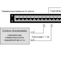 Where are the boundaries between these categories of consumers?
 What is an asset directory
 Free programs for Windows free download