DIY weapon chronograph. Cheap do-it-yourself chronograph for pneumatics. How a self-made chronograph works
In my first publication, I want to tell you how I assembled a chronograph in a couple of evenings from cheap and accessible parts. As you probably already guessed from the name, this device is used to measure the speed of a bullet in air (and not so) rifles and is useful for monitoring its technical condition.
1. Parts and accessories
- Chinese Digispark - 80 rubles at the time of purchase
- Segment display on TM1637 - 90 rubles at the time of purchase
- IR LEDs and IR phototransistors (10 pairs) - 110 rubles at the time of purchase, we need 2 pairs
- Resistors 220 Ohm (100pcs) - 70 rubles at the time of purchase, we only need 2 pieces
- Wires - finding offline for free is not a problem
- piece of plastic water pipe over 10cm long (diameter to taste) - just as easy to find
- Soldering accessories
- Multimeter (optional)
1.1. Digispark
It is a simple miniature Arduino-compatible board with an ATtiny85 on board. We read how to connect to the Arduino IDE on the official website of the project, where you can also find drivers for it. There are two main types of this board: with microUSB and more brutal with a USB connector, wired right on the board.
My chronograph does not have its own power supply, so I chose the first board option. A built-in battery/accumulator will greatly increase the price, while adding almost nothing to usability. Almost everyone has a power bank and a cable for charging the phone.
Specifications of course inherited from ATtiny85, its capabilities in our case are enough with the head. In fact, the MK in the chronograph does nothing but interrogate the two sensors and control the display. For those who come across Digispark for the first time, I have summarized the most important features in a table:
I use this plate as a cheat sheet when developing various devices based on this board. As you probably noticed, the pin numbering for the analogRead() function is different, this should be taken into account. And one more feature: a pull-up resistor of 1.5 kOhm hangs on the third pin, because. it is used in USB.
1.2. Display based on TM1637
The next important detail is a digital display on which information will be displayed. Any display can be used, my choice is due only to the cheapness and ease of working with it. In principle, you can refuse the display altogether and output data via cable to a PC, then the device will become even cheaper. To work, you need the DigitalTube library. The subject I linked to at the beginning of the post is a clone of the Grove display. Front view:

The distance between the digits is the same, so when the colon is off, the numeric values are read normally. Together with the standard library, an example is supplied that works with Digispark without dancing with a tambourine:

All the standard library can do is print the numbers 0-9 and letters a-f, as well as change the brightness of the entire display. The value of a digit is given by the display(int 0-3, int 0-15) function.
Express course on using the display
// 1. Declare header file #include
If you try to display a character with a code outside the boundaries, then the display shows nonsense, which is not static, so you won’t be able to cheat to display special characters (degrees, minus) without a tambourine:

This did not suit me, since in my chronograph I wanted to provide for the output of not only speed, but also the energy of the bullet (calculated based on the mass pre-written in the sketch), these two values \u200b\u200bshould be output sequentially. To understand what the display is showing at a given moment in time, you need to somehow separate these two values visually, for example, using the “J” symbol. Of course, you can stupidly use the colon symbol as a flag indicator, but this is not true and not kosher) Therefore, I got into the library and, based on the display function, made the setSegments(byte addr, byte data) function, which lights up in the figure with the number addr segments encoded in data:
Void setSegments(byte addr, byte data) ( tm1637.start(); tm1637.writeByte(ADDR_FIXED); tm1637.stop(); tm1637.start(); tm1637.writeByte(addr|0xc0); tm1637.writeByte(data) ; tm1637.stop(); tm1637.start(); tm1637.writeByte(tm1637.Cmd_DispCtrl); tm1637.stop(); )
Segments are encoded extremely simply: the least significant bit of data is responsible for the uppermost segment, and so on. clockwise, the seventh bit is responsible for the central segment. For example, the character "1" is encoded as 0b00000110. The eighth, most significant bit is used only in the second digit and is responsible for the colon, in all other digits it is ignored. To make my life easier, as any lazy IT specialist should, I automated the process of obtaining character codes using excel:

Now you can easily do this:


Let's say HELLO
#include
1.3. Sensors
Here, unfortunately, I can’t say anything special, because on the product page there is not a word about the characteristics or at least markings by which one could dig up the datasheet. Typical noname. Only the wavelength of 940nm is known.
At the price of one LED, I determined that a current of more than 40mA is fatal for them, and the supply voltage should be below 3.3V. The phototransistor is slightly transparent and reacts to light
2. Preparation of parts and assembly
The circuit is very simple and uncomplicated, of all the digispark-a pins, we only need P0, P1 - to work with the display, as well as P2 - to work with sensors:
As you can see, one resistor limits the current on the LEDs, the second pulls P2 to ground. The phototransistors are connected in series, so passing a bullet in front of any optocoupler results in a decrease in voltage across P2. By registering two consecutive power surges and measuring the time between them, we can determine the speed of the bullet (knowing the distance between the sensors, obviously). Using a single measuring pin has another plus - there is no required direction of the bullet, you can shoot from both ends. We will collect from this handful of parts:

I went down the path of miniaturization and decided to make a sandwich using a piece of breadboard:

The whole sandwich was filled with hot glue for strength:


It remains only to place the sensors in the tube and solder the wires:

The photo shows that I placed an additional electrolyte at 100mKf in parallel with the LEDs, so that when powered from the power bank there were no ripples of the IR diodes.

Pin P2 was chosen as an input for a reason. Let me remind you that P3 and P4 are used in USB, so using P2 makes it possible to flash the device already assembled. Secondly, P2 is an analog input, so you can not use interrupts, but simply measure the difference in the cycle between the previous and current value on it, if the difference is above a certain threshold, then the bullet passes between one of the optocouplers. But there is one software trick, without which the above scheme will not take off, we will talk about it later.
3. Firmware
3.1. A few words about prescaler
Prescaler is a frequency divider, by default in arduino-like boards it is 128. The maximum ADC polling frequency depends on the value of this value, by default for a 16 MHz controller it turns out 16/128 = 125 kHz. Each digitization takes 13 operations, so the maximum pin polling frequency is 9600 kHz (in theory, in practice it really does not exceed 7 kHz). Those. the interval between measurements is approximately 120 μs, which is very, very much. A bullet flying at a speed of 300 m / s will fly 3.6 cm during this time - the controller simply does not have time to detect the fact that the bullet passes through the optocoupler. For normal operation, you need an interval between measurements of at least 20 µs, the required divisor value for this is 16. I went even further and use a divider of 8 in my device, this is done as follows:#ifndef cbi #define cbi(sfr, bit) (_SFR_BYTE(sfr) &= ~_BV(bit)) #endif #ifndef sbi #define sbi(sfr, bit) (_SFR_BYTE(sfr) |= _BV(bit)) # endif void setup() ( sbi(ADCSRA,ADPS2); cbi(ADCSRA,ADPS1); cbi(ADCSRA,ADPS0); ... )
Real measurements of the analogRead interval on different dividers:

3.2. Final sketch
I will not describe the code in detail, it is already well documented. Instead, I'm in in general terms I will describe the algorithm of its work. So, the whole logic comes down to the following steps:- The first cycle - the difference between the current and previous value on the pin is measured
- If the difference is greater than the specified threshold, then exit the loop and remember the current time (micros())
- Second cycle - similar to the previous one + time counter in the cycle
- If the counter has reached the specified value, then inform about the error and go to the beginning. This allows the loop not to go into eternity if the bullet for some reason was not noticed by the second sensor.
- If the counter has not overflowed and the difference in values is greater than the threshold, then we measure the current time (micros())
- Based on the difference in time and distance between the sensors, we calculate the speed and display it on the screen
- Go to start
Actually, the whole code
/* * Bullet speed chronograph, SinuX 03/23/2016 */ #include
4. Examples of work
When properly connected, the device took off almost immediately, the only drawback found is that it reacts negatively to LED and fluorescent lighting (pulse frequency is about 40 kHz), hence spontaneous errors may appear. In total, the device has 3 modes of operation:Greeting after turning on and switching to the standby mode for a shot (the screen is filled with stripes):

In case of an error, "Err" is displayed, and again switching to standby mode:

Well, the speed measurement itself:

After the shot, first the bullet speed is shown (with the symbol "n"), then - the energy (symbol "J"), and the energy is calculated with an accuracy of one decimal place (on the gif you can see that when the joules are shown, the colon is on). I haven’t been able to find a prettier case yet, so I just filled everything with thermal snot:
Perhaps that's all I have, I hope it was useful to someone.
In my first publication, I want to tell you how I assembled a chronograph in a couple of evenings from cheap and accessible parts. As you probably already guessed from the name, this device is used to measure the speed of a bullet in air (and not so) rifles and is useful for monitoring its technical condition.
1. Parts and accessories
- Chinese Digispark - 80 rubles at the time of purchase
- Segment display on TM1637 - 90 rubles at the time of purchase
- IR LEDs and IR phototransistors (10 pairs) - 110 rubles at the time of purchase, we need 2 pairs
- Resistors 220 Ohm (100pcs) - 70 rubles at the time of purchase, we only need 2 pieces
- Wires - finding offline for free is not a problem
- A piece of plastic water pipe over 10 cm long (diameter to taste) - just as easy to find
- Soldering accessories
- Multimeter (optional)
1.1. Digispark
It is a simple miniature Arduino-compatible board with an ATtiny85 on board. We read how to connect to the Arduino IDE on the official website of the project, where you can also find drivers for it. There are two main types of this board: with microUSB and more brutal with a USB connector, wired right on the board.
My chronograph does not have its own power supply, so I chose the first board option. A built-in battery/accumulator will greatly increase the price, while adding almost nothing to usability. Almost everyone has a power bank and a cable for charging the phone.
Specifications of course inherited from ATtiny85, its capabilities in our case are enough with the head. In fact, the MK in the chronograph does nothing but interrogate the two sensors and control the display. For those who come across Digispark for the first time, I have summarized the most important features in a table:
I use this plate as a cheat sheet when developing various devices based on this board. As you probably noticed, the pin numbering for the analogRead() function is different, this should be taken into account. And one more feature: a pull-up resistor of 1.5 kOhm hangs on the third pin, because. it is used in USB.
1.2. Display based on TM1637
The next important detail is a digital display on which information will be displayed. Any display can be used, my choice is due only to the cheapness and ease of working with it. In principle, you can refuse the display altogether and output data via cable to a PC, then the device will become even cheaper. To work, you need the DigitalTube library. The subject I linked to at the beginning of the post is a clone of the Grove display. Front view:
The distance between the digits is the same, so when the colon is off, the numeric values are read normally. Together with the standard library, an example is supplied that works with Digispark without dancing with a tambourine:
All that the standard library can do is print the numbers 0-9 and the letters a-f, as well as change the brightness of the entire display. The value of a digit is given by the display(int 0-3, int 0-15) function.
Express course on using the display
// 1. Declare header file #include
If you try to display a character with a code outside the boundaries, then the display shows nonsense, which is not static, so you won’t be able to cheat to display special characters (degrees, minus) without a tambourine:
This did not suit me, since in my chronograph I wanted to provide for the output of not only speed, but also the energy of the bullet (calculated based on the mass pre-written in the sketch), these two values \u200b\u200bshould be output sequentially. To understand what the display is showing at a given moment in time, you need to somehow separate these two values visually, for example, using the “J” symbol. Of course, you can stupidly use the colon symbol as a flag indicator, but this is not true and not kosher) Therefore, I got into the library and, based on the display function, made the setSegments(byte addr, byte data) function, which lights up in the figure with the number addr segments encoded in data:
Void setSegments(byte addr, byte data) ( tm1637.start(); tm1637.writeByte(ADDR_FIXED); tm1637.stop(); tm1637.start(); tm1637.writeByte(addr|0xc0); tm1637.writeByte(data) ; tm1637.stop(); tm1637.start(); tm1637.writeByte(tm1637.Cmd_DispCtrl); tm1637.stop(); )
Segments are encoded extremely simply: the least significant bit of data is responsible for the uppermost segment, and so on. clockwise, the seventh bit is responsible for the central segment. For example, the character "1" is encoded as 0b00000110. The eighth, most significant bit is used only in the second digit and is responsible for the colon, in all other digits it is ignored. To make my life easier, as any lazy IT specialist should, I automated the process of obtaining character codes using excel:
Now you can easily do this:
Let's say HELLO
#include
1.3. Sensors
Here, unfortunately, I can’t say anything special, because on the product page there is not a word about the characteristics or at least markings by which one could dig up the datasheet. Typical noname. Only the wavelength of 940nm is known.
At the price of one LED, I determined that a current of more than 40mA is fatal for them, and the supply voltage should be below 3.3V. The phototransistor is slightly transparent and reacts to light
2. Preparation of parts and assembly
The circuit is very simple and uncomplicated, of all the digispark-a pins, we only need P0, P1 - to work with the display, as well as P2 - to work with sensors:
As you can see, one resistor limits the current on the LEDs, the second pulls P2 to ground. The phototransistors are connected in series, so passing a bullet in front of any optocoupler results in a decrease in voltage across P2. By registering two consecutive power surges and measuring the time between them, we can determine the speed of the bullet (knowing the distance between the sensors, obviously). Using a single measuring pin has another plus - there is no required direction of the bullet, you can shoot from both ends. We will collect from this handful of parts:
I went down the path of miniaturization and decided to make a sandwich using a piece of breadboard:
The whole sandwich was filled with hot glue for strength:
It remains only to place the sensors in the tube and solder the wires:
The photo shows that I placed an additional electrolyte at 100mKf in parallel with the LEDs, so that when powered from the power bank there were no ripples of the IR diodes.
Pin P2 was chosen as an input for a reason. Let me remind you that P3 and P4 are used in USB, so using P2 makes it possible to flash the device already assembled. Secondly, P2 is an analog input, so you can not use interrupts, but simply measure the difference in the cycle between the previous and current value on it, if the difference is above a certain threshold, then the bullet passes between one of the optocouplers. But there is one software trick, without which the above scheme will not take off, we will talk about it later.
3. Firmware
3.1. A few words about prescaler
Prescaler is a frequency divider, by default in arduino-like boards it is 128. The maximum ADC polling frequency depends on the value of this value, by default for a 16 MHz controller it turns out 16/128 = 125 kHz. Each digitization takes 13 operations, so the maximum pin polling frequency is 9600 kHz (in theory, in practice it really does not exceed 7 kHz). Those. the interval between measurements is approximately 120 μs, which is very, very much. A bullet flying at a speed of 300 m / s will fly 3.6 cm during this time - the controller simply does not have time to detect the fact that the bullet passes through the optocoupler. For normal operation, you need an interval between measurements of at least 20 µs, the required divisor value for this is 16. I went even further and use a divider of 8 in my device, this is done as follows:#ifndef cbi #define cbi(sfr, bit) (_SFR_BYTE(sfr) &= ~_BV(bit)) #endif #ifndef sbi #define sbi(sfr, bit) (_SFR_BYTE(sfr) |= _BV(bit)) # endif void setup() ( sbi(ADCSRA,ADPS2); cbi(ADCSRA,ADPS1); cbi(ADCSRA,ADPS0); ... )
Real measurements of the analogRead interval on different dividers:
3.2. Final sketch
I will not describe the code in detail, it is already well documented. Instead, I will describe in general terms the algorithm of its operation. So, the whole logic comes down to the following steps:- The first cycle - the difference between the current and previous value on the pin is measured
- If the difference is greater than the specified threshold, then exit the loop and remember the current time (micros())
- Second cycle - similar to the previous one + time counter in the cycle
- If the counter has reached the specified value, then inform about the error and go to the beginning. This allows the loop not to go into eternity if the bullet for some reason was not noticed by the second sensor.
- If the counter has not overflowed and the difference in values is greater than the threshold, then we measure the current time (micros())
- Based on the difference in time and distance between the sensors, we calculate the speed and display it on the screen
- Go to start
Actually, the whole code
/* * Bullet speed chronograph, SinuX 03/23/2016 */ #include
4. Examples of work
When properly connected, the device took off almost immediately, the only drawback found is that it reacts negatively to LED and fluorescent lighting (pulse frequency is about 40 kHz), hence spontaneous errors may appear. In total, the device has 3 modes of operation:Greeting after turning on and switching to the standby mode for a shot (the screen is filled with stripes):
In case of an error, "Err" is displayed, and again switching to standby mode:
Well, the speed measurement itself:
After the shot, first the bullet speed is shown (with the symbol "n"), then - the energy (symbol "J"), and the energy is calculated with an accuracy of one decimal place (on the gif you can see that when the joules are shown, the colon is on). I haven’t been able to find a prettier case yet, so I just filled everything with thermal snot:
Perhaps that's all I have, I hope it was useful to someone.
The chronograph is a versatile instrument capable of measuring the speed of small objects. It is most convenient to set up and test pneumatics with frame-type chronographs. They can detect the movement of bullets, crossbow bolts, arrows, slingshot staples. You can make a chronograph for pneumatics with your own hands or purchase it in specialized stores.
Chronograph types
Measuring the starting speed of a bullet with a chronograph allows you to determine the power of a pistol or rifle, select the right bullets, calculate ballistic corrections, and compare the speed at the beginning and after upgrading the weapon.
 There are different types of chronographs. The inflatable model takes up little space and fits easily in the pocket of the case, and it also consumes less energy. For a particular type of weapon, you may need adapter. This type does not depend on lighting and is convenient to use in nature. Aimed shooting can be carried out together with the device. For CO2, this model is not suitable.
If you have an impressive arsenal, it is better to purchase frame chronograph not to buy a large number of adapters. This type of device works well with CO2, has a connector for an external power supply. Armor allows you to measure indicators at different distances without fear of damaging the mechanism. The presence of an additional screen helps to get results quickly.
There are also large frame models that expand the number of possibilities. This option is suitable for use with any type of weapon, it is convenient for a stationary connection to the network. Alternatively, the chronograph can be powered by eight AA batteries. Unlike the small model, the large machine has built-in front type indicator. You can optionally install a removable screen. Using the USB adapter, you can transfer measurement data from the device to a computer.
Buying a Chronograph for Pneumatics
You can buy various types of chronographs in Moscow and St. Petersburg in the following stores:
- Airgun Store - at a price of 3500 to 24 thousand rubles;
- Diada Arms - at a price of 4 thousand to 13 thousand rubles;
- Pnevmat 24 - at a price of 4 thousand to 7 thousand rubles;
- Oxotnika.net - at a price of 3 thousand to 20 thousand rubles.
These stores also offer a variety of chronograph parts and accessories. You can purchase a more budget model on AliExpress at a price of 3 thousand rubles. or buy a used one, for example, on the Guns.ru or Avito portal at a price of 1500 rubles.
Do-it-yourself frame-type chronograph for pneumatics
The chronograph records the bullet's flight time between multiple sensors and calculates its speed. The device consists of three parts:
- working area, passing a bullet through itself;
- a circuit that conducts calculations;
- display showing calculated results.
Schemes for a chronograph can be different in cost, functionality and design. The simplest sensors read the light falling on them, the intensity of which changes as the shadow-casting bullet moves. Light-sensitive elements are part of many homemade and factory made chronographs.
The self-made device has several advantages:

Along with this, the device has its own limitations:
- cumbersome design;
- the need for ingress protection for the face of the work area;
- influence of weather conditions and lighting on work;
- sensitivity of the optics scheme to significant mechanical impacts, including bullet fragments and ricochets;
- output of false readings when appearing in the camera foreign objects, such as snow, insects, or mechanical fragments;
- the influence of the flight path on the recorded bullet speed (moving the object diagonally reduces the indicator).
Components and materials for assembly
The total number of parts and their complexity depend on the user's skill level in designing and installing circuits. Some components are obligatory for any kind of assembly:
- LEDs to create an artificial light source;
- soldering iron with flux and solder for fixing wires and installing a microcircuit;
- optical receivers for reading the level of illumination during the passage of a bullet through the LEDs;
- a microcircuit for determining the time of flight of a bullet and calculating the speed;
- display for displaying measurement results;
- rectangular hollow body, closed on four sides (it is better to choose a solid metal product that will be resistant to shock).
Chronograph Mounting Steps
Elements of the microcircuit and sensors must be protected or located in places that will not be accessible for a direct hit by a bullet. Under them, you need to prepare a place in the case in advance. The inside of the product is covered with a dark paint that does not create glare in order to avoid unnecessary operation of the device and increase its sensitivity.
Light-sensitive elements and the LEDs themselves are mounted in pre-marked holes. The photodetectors should be slightly recessed, and the LEDs should bulge slightly into the inside of the chronograph. This arrangement will reduce the intensity of external light falling on the device.
At the next stage, the board is installed and connected to the sensors, sections are marked for power supply. For self-drawing up a diagram, you can use Fig. one.

Rice. 1 Chronograph chip
When the main components are assembled, the circuit will need to be protected from mechanical stress and moisture. For this task, a plastic box for a printed circuit board is suitable, which will have outputs to the battery, display and sensors.
How a self-made chronograph works
As a power source for the device, batteries, accumulators, a power supply connected to the network can be used. An autonomous source is more profitable and convenient, since in most cases weapon tuning is carried out outside the home.
The speed measurement process goes through three stages:
- the bullet passes through the axis of the initial sensor, resetting the time counter in the microprocessor;
- after the bullet crosses the axis of the next sensor, the time stops and the data is transmitted for calculations;
- the microprocessor performs calculations and displays the speed indicators on the display.
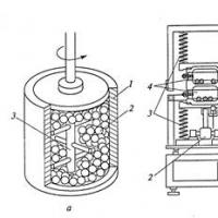
The operation of the frame-type chronograph can be seen visually in Fig. 2.

Rice. 2 Chronograph operation diagram
In order to assemble a chronograph yourself, you will need knowledge and experience in electrical engineering, soldering and designing electrical circuits. You can make the task easier by ordering the manufacture of a microcircuit to an electronics master. A self-assembled chronograph will cost much less than a purchased version.
In this article, we will look at how you can make a simple chronograph from inexpensive and affordable parts. fixture necessary in order to measure the speed of a bullet from a rifle. These numbers are needed in order to determine the condition of the rifle, because over time, some pneumatic components wear out and need to be replaced.
Preparing necessary materials and tools:
- Chinese Digispark (it cost 80 rubles at the time of purchase);
- segment type display on TM1637 (it cost 90 rubles when buying);
- infrared LEDs and phototransistors (10 pairs) - the cost was 110 rubles;
- one hundred 220 ohm resistors cost 70 rubles, but only two of them will be needed.
That's all, this is the entire list of items that you will need to buy. By the way, resistors can also be found in the old household appliances. You can bet more at face value, but not less. As a result, you can meet 350 rubles, but this is not so much, given that the factory chronograph will cost at least 1000 rubles, and the assembly there is much worse than ours homemade.
Among other things, you need to stock up on such details as:
- wires;
- a piece of pipe at least 10 cm long (plastic plumbing is suitable);
- all for soldering;
- multimeter (optional).
The first three details described have their own nuances, so each of them needs to be considered separately.
Digispark
This item is a miniature board that is compatible with Arduino, she has an ATtiny85 on board. How to connect this element to the Arduino IDE, you can read on, you can also download drivers for it there.
This board has several options, one uses microUSB, and the other is equipped with a USB connector that is wired right on the board. Due to the fact that the homemade product does not have an individual power supply, the author chose the first version of the board. If you install a battery or accumulator in a homemade product, this will greatly increase its price, and will not greatly affect practicality. And almost everyone has a cable for charging a mobile and Power bank.

As for the characteristics, they are similar to ATtiny85, here its capabilities are more than enough. The microcontroller in the chronograph only polls the sensors and controls the display.
If you have never met Digispark, the most important nuances can be seen in the table.

It is important to take into account the fact that the pin numbering for the analogRead() function is different. And on the third pin there is a pull-up resistor with a nominal value of 1.5 kOhm, since it is used in USB.
A few words about the display
Any display for homemade products can be used, but the author opted for a cheap option. To make the device even cheaper, the display can be completely abandoned. Data can simply be output to a computer through a cable. It will be needed here. The considered display is a copy of the display.
How the display looks front and back can be seen in the photo.


Since the distances between the digits are the same, with the colon turned off, the digits are read without problems. The standard library is capable of outputting numbers in the range 0-9. letters in the range a-f, and there is also the possibility to change the brightness of the entire display. Digit values can be set using the display(int 0-3, int 0-15) function.

How to use the display
// 1. Declare a header file
#include
// 2. Set pins
#define CLK 0
#define DIO 1
// 3. Declare an object
TM1637 tm1637(CLK, DIO);
// 4. Initialize
void setup()(
tm1637.init();
tm1637.set(6); // Brightness
}
// 5. Use
void loop() (
// Display the number x on the display
int x = 1234;
tm1637.display(0, x / 1000);
tm1637.display(1, x / 100% 10);
tm1637.display(2, x / 10% 10);
tm1637.display(3, x % 10);
delay(500);
}
If you try to go beyond the values, then the display will show confusion, which, plus everything else, is not static. Therefore, to display special characters, such as degrees, minuses, etc., you will have to tinker.

The author wanted the display to show the finished energy of the bullet's flight, which would be calculated depending on the speed of the bullet and its mass. As planned, the values should have been displayed sequentially, and in order to understand where which one is, they need to be marked somehow, for example, using the letter “J”. As a last resort, you can simply use the colon, but this did not suit the author, and he got into the library. As a result, on the basis of the display function, the setSegments(byte addr, byte data) function was made, it lights segments encoded in data in the digit with the addr number:
{
tm1637.start();
tm1637.stop();
tm1637.start();
tm1637.writeByte(addr|0xc0);
tm1637.writeByte(data);
tm1637.stop();
tm1637.start();
tm1637.stop();
}
Such segments are encoded quite simply, the low data bit is responsible for the upper segment, and then clockwise, the 7th bit is responsible for the middle segment. The character "1" when encoded looks like 0b00000110. The eighth most significant bit is responsible for the colon, it is used in the second digit, and is ignored in all others. Subsequently, the author automated the process of obtaining codes using Excel.

What happened in the end, you can see in the photo


#include
#define CLK 0
#define DIO 1
TM1637 tm1637(CLK, DIO);
void setSegments(byte addr, byte data)
{
tm1637.start();
tm1637.writeByte(ADDR_FIXED);
tm1637.stop();
tm1637.start();
tm1637.writeByte(addr|0xc0);
tm1637.writeByte(data);
tm1637.stop();
tm1637.start();
tm1637.writeByte(tm1637.Cmd_DispCtrl);
tm1637.stop();
}
void setup()(
tm1637.init();
tm1637.set(6);
}
void loop() (
// Output Hello
setSegments(0, 118);
setSegments(1, 121);
setSegments(2, 54);
setSegments(3, 63);
delay(500);
}
And finally, the sensors
Precise information about the sensors is not provided, it is only known that they have a wavelength of 940 nm. During the experiments, it was found that the sensors are not able to withstand a current of more than 40 mA. As for the supply voltage, it should not be higher than 3.3V. As for the phototransistor, it has a slightly transparent case and reacts to light.

Let's start assembling and setting up a homemade product:
Step one. Assembly
Everything is assembled according to a very simple scheme. Of all the pins, only P0, P1 and P2 will be needed. The first two are used for the display, and P2 is needed for the sensors to work.
As you can see, one resistor is used to limit the current for the LEDs, while the second pulls P2 to ground. Due to the fact that the phototransistors are connected in parallel, when the bullet passes in front of any optocoupler, the voltage across P2 will drop. To determine the speed of a bullet, you need to know the distance between the sensors, measure two power surges and determine the time during which they occurred.
Due to the fact that only one pin will be used, it does not matter which side to shoot from. The phototransistors will notice the bullet anyway.


Everything is assembled from the details that can be seen in the photo. To assemble everything, the author decided to use a breadboard. Then the whole structure for strength was filled with hot-melt adhesive. The sensors are placed on the pipe and wires are soldered to them.
To prevent the diodes from pulsing when powered by a power bank, the author installed a 100 uF electrolyte in parallel with the LEDs.


It is also important to note that the P2 pin was chosen for a reason, the fact is that P3 and P4 are used in USB, so now with the help of P2 it is possible to flash a homemade product after assembly.
P2 is also an analog input, so there is no need to use an interrupt. You can simply measure the readings between the current and the previous value, if the difference becomes above a certain threshold, then at that moment the bullet just passes near the optocoupler.
Step two. Firmware
Prescaler is a frequency divider, in standard cases in boards like Arduino it is 128. This figure affects how often the ADC is polled. That is, for the default 16 MHz, 16/128 = 125 kHz comes out. Each digitization consists of 13 operations, so the pin can be polled at a maximum rate of 9600 kHz. In practice, this is no more than 7 kHz. As a result, the interval between measurements is 120 μs, which is too long for homemade work. If the bullet flies at a speed of 300 m / s, it will cover a distance of 3.6 cm during this time, that is, the controller simply will not be able to notice it. For everything to work properly, the interval between measurements must be at least 20 µs. To do this, the divisor value must be equal to 16. The author made a divisor of 8, how to do this can be seen below.
 Basic technologies for obtaining nanomaterials
 How to tell the time in English?
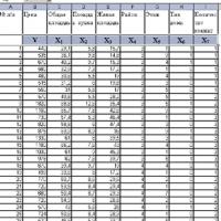 Introduction to Multivariate Statistical Analysis
 Presentation of the analytical report of the history teacher
 Presentation on the topic "atherosclerosis"
 History of number systems
 Apple in mythology and Russian folklore