Sensor for indicating the water level in the tank. How to make a device for automatically maintaining the water level with your own hands. Water level indicators
Greetings!
I decided to post a small article in case it might be useful to someone like me))
I built a small, simple device to maintain a constant water level in a container. The circuit was taken from the Internet and repeated only with the addition of an elementary parametric voltage stabilizer, because According to the technical specifications, the device should be powered by 24V, and the entire circuit and relay should be powered by 12V.
Three-electrode water level sensor.
A diagram of the pump control device is proposed. This diagram is from a set offered by “Master KIT”. The pump control device will allow you to automate the operation of the country pump, with the help of which water flows into the shower tank. The operating principle of the “smart assistant” is as follows: when the water level in the shower tank drops below a certain level L, the pump turns on and begins to pump water into the container. When the water level reaches the set level H, the device turns off the pump.
This device can be used in the countryside, in country house, cottage. The electrical circuit diagram of the device is shown in the figure.
The circuit is simple and does not need to be configured.
Water has electrical resistance. While there is no water in the container, transistors T1 and T2 are closed, and a high voltage is present at the collector of transistor T1. This high voltage, entering through diode D1 to the base of transistor T3, opens it and transistor T4, which leads to the activation of the executive relay, to the power contacts of which the pump is connected. The pump begins to pump water into the container. The LED turns on, indicating the operation of the pump. When the water level reaches sensor L, transistor T1 opens and the voltage at its collector drops. However, the pump continues to work because voltage is supplied to the base of transistor T3 through resistor R8 and maintains the switch T3-T4 in the open state. When the water level reaches the "H" sensor, transistor T2 opens, and T3 flows to the base of the transistor low level. The TZ-T4 key is closed - the relay is turned off. Only when the water level drops below level “L” again will the relay turn on again. Structurally, the device is made on a printed circuit board made of foil fiberglass with dimensions of 61x41 mm. As "L" and "H" sensors, you can use available materials, such as half-inch copper plumbing nuts firmly attached to insulated wires. Turn on devices. Connect the sensor wires to the board and place them in an experimental container of the same height as the shower tank used at the dacha as follows: “COM” at the bottom (if the container is iron, then you can connect this wire to the body of the container); "L" - at the desired lower water level (pump activation level); "H" - at the pump shutdown level. Connect the device to the power source, observing the polarity. Do not connect the mains voltage and the pump yet. Turn on the power. The indicator LED should light up and the relay should “click”, connecting the pump. Pour water into the container. When the water level reaches the "H" sensor, the relay should turn off. Empty the water from the container. When the water level drops just below the "L" sensor, the relay should turn on. Now you can finally install the sensors on a real object and, being careful, connect 220 V and a pump to the contacts of the circuit.
The advantage of this scheme over simpler ones is the use of a relay with only one contact. Almost all similar simpler circuits use 2 groups of contacts.
Substitutions are possible in the circuit: any bipolar transistors with the specified conductivity. I installed V9014 and V9015, but VT5 in the stabilizer - KT805BM in TO-220 with a small radiator. The presence of a radiator is mandatory - the heating is very intense. I also put it on thermal paste. Diodes - any silicon. Capacitors - any with a voltage of at least 16V for C1, C2 and 40V for C3. Bridge (or diodes in the bridge) - for a voltage not lower than the supply voltage and a current of at least 200 mA. The current consumption of the circuit when the relay was activated was 150 mA at a supply voltage of 24 V. When powered by DC, you can throw out the bridge. When powered from a 12V (constant) source, you can remove the entire stabilizer circuit.
First version.
The board used a combination of DIP and SMD components. The first version of the board, one of the devices is soldered on it. The board of the second one has been slightly modified: the bridge has been removed from the board, the use of a transistor in the stabilizer in the TO-220 case is provided, there are more SMD elements, the width of the tracks has been increased.
The diode bridge is soldered on a separate small strip.
Water supply and drainage is an integral part of everyday life and production. Almost everyone who has been involved in farming or home improvement has at least once encountered the problem of maintaining the water level in one container or another. Some people do this manually by opening and closing valves, but it is much easier and more efficient to use an automatic water level sensor for this purpose.
Types of level sensors
Depending on the tasks assigned, contact and non-contact sensors are used to monitor the liquid level. The former, as one might guess from their name, have contact with the liquid, the latter receive information remotely, using indirect measurement methods - transparency of the medium, its capacity, electrical conductivity, density, etc. According to the principle of operation, all sensors can be divided into 5 main types:
- Float
- Electrode.
- Hydrostatic.
- Capacitive.
- Radar.
The first three can be classified as contact-type devices, since they directly interact with working environment(liquid), the fourth and fifth are non-contact.
Float sensors
Perhaps the simplest in design. They are a float system that is located on the surface of the liquid. As the level changes, the float moves, one way or another closing the contacts of the control mechanism. The more contacts there are along the path of the float, the more accurate the indicator readings:
Operating principle of a float water level sensor in a tank
The figure shows that the indicator readings of such a device are discrete, and the number of level values depends on the number of switches. In the diagram above there are two of them - upper and lower. This, as a rule, is quite enough to automatically maintain the level in a given range.
There are float devices for continuous remote monitoring. In them, the float controls the rheostat motor, and the level is calculated based on the current resistance. Until recently, such devices were widely used, for example, to measure the amount of gasoline in car fuel tanks:
Rheostatic level meter device, where:
- 1 – wire rheostat;
- 2 – rheostat slider, mechanically connected to the float.
Electrode level sensors
Devices of this type use the electrical conductivity of a liquid and are discrete. The sensor consists of several electrodes various lengths immersed in water. Depending on the level in the liquid, there is one or another number of electrodes.
Three-electrode system of liquid level sensors in the tank
In the figure above, the two right sensors are immersed in water, which means that there is water resistance between them - the pump is stopped. As soon as the level drops, the middle sensor will be dry and the circuit resistance will increase. The automation will start the boost pump. When the container is full, the shortest electrode will fall into the water, its resistance relative to the common electrode will decrease and the automation will stop the pump.
It is quite clear that the number of control points can easily be increased by adding additional electrodes and corresponding control channels to the design, for example, for overflow or dryness alarms.
Hydrostatic control system
Here the sensor is an open tube in which a pressure sensor of one type or another is installed. As the level increases, the height of the water column in the tube changes, and therefore the pressure on the sensor:
Operating principle of hydrostatic liquid level control system
Such systems have a continuous characteristic and can be used not only for automatic control, but also for remote level control.
Capacitive measurement method
Operating principle of a capacitive sensor with a metal (left) and dielectric bath
Induction pointers work on a similar principle, but in them the role of a sensor is played by a coil, the inductance of which changes depending on the presence of liquid. The main disadvantage of such devices is that they are only suitable for monitoring substances (liquids, bulk materials, etc.) that have a sufficiently high magnetic permeability. Inductive sensors are practically not used in everyday life.
Radar control
The main advantage of this method is the lack of contact with the working environment. Moreover, the sensors can be quite far away from the liquid, the level of which needs to be controlled - meters. This allows radar-type sensors to be used to monitor extremely aggressive, toxic or hot liquids. The principle of operation of such sensors is indicated by their very name - radar. The device consists of a transmitter and receiver assembled in one housing. The first emits one or another type of signal, the other receives the reflected one and calculates the delay time between the sent and received pulses.
Operating principle of ultrasonic radar type level switch
The signal, depending on the assigned tasks, can be light, sound, or radio emission. The accuracy of such sensors is quite high – millimeters. Perhaps the only drawback is the complexity of radar monitoring equipment and its fairly high cost.
Homemade liquid level regulators
Due to the fact that some of the sensors are extremely simple in design, creating a water level switch with your own hands is not difficult at all. Working together with water pumps, such devices will allow you to fully automate the process of pumping water, for example, into a country water tower or autonomous system drip irrigation.
Float automatic pump control
To implement this idea, a homemade reed switch water level sensor with a float is used. It does not require expensive and scarce components, is easy to repeat and is quite reliable. First of all, it is worth considering the design of the sensor itself:
Design of a two-level float sensor for water in the tank
It consists of a float 2 itself, which is fixed to a movable rod 3. The float is on the surface of the water and, depending on its level, moves together with the rod and the permanent magnet 5 up/down in guides 4 and 5. In the lower position, when the liquid level is minimal, the magnet closes the reed switch 8, and in the upper position (the tank is full) - the reed switch 7. The length of the rod and the distance between the guides are selected based on the height of the water tank.
All that remains is to assemble a device that will automatically turn the boost pump on and off depending on the state of the contacts. Its diagram looks like this:
Water pump control circuit
Assume that the tank is completely full and the float is in the up position. Reed switch SF2 is closed, transistor VT1 is closed, relays K1 and K2 are disabled. The water pump connected to connector XS1 is de-energized. As the water flows, the float, and along with it the magnet, will lower, the reed switch SF1 will open, but the circuit will remain in the same state.
As soon as the water level drops below the critical level, the reed switch SF1 closes. Transistor VT1 will open, relay K1 will operate and become self-locking with contacts K1.1. At the same time, contacts K1.2 of the same relay will supply power to starter K2, which turns on the pump. Water pumping began.
As the level increases, the float will begin to rise, contact SF1 will open, but the transistor blocked by contacts K1.1 will remain open. As soon as the container is filled, contact SF2 closes and forcibly closes the transistor. Both relays will release, the pump will turn off, and the circuit will go into standby mode.
When repeating the circuit in place of K1, you can use any low-power electromagnetic relay with an operating voltage of 22-24 V, for example, RES-9 (RS4.524.200). An RMU (RS4.523.330) or any other with an operating voltage of 24 V, the contacts of which can withstand the starting current of the water pump, is suitable as K2. Reed switches can be any type that operates to close or switch.
Level switch with electrode sensors
For all its advantages and simplicity, the previous design of a level gauge for tanks also has a significant drawback - mechanical components that operate in water and require constant maintenance. This disadvantage is absent in the electrode design of the machine. It is much more reliable than the mechanical one, does not require any maintenance, and the circuit is not much more complicated than the previous one.
Here, three electrodes made of any conductive stainless material are used as sensors. All electrodes are electrically isolated from each other and from the container body. The design of the sensor is clearly visible in the figure below:
Three-electrode sensor design, where:
- S1 – common electrode (always in water)
- S2 – minimum sensor (tank empty);
- S3 – maximum level sensor (tank full);
The pump control circuit will look like this:
Scheme of automatic pump control using electrode sensors
If the tank is full, then all three electrodes are in water and the electrical resistance between them is small. In this case, transistor VT1 is closed, VT2 is open. Relay K1 is turned on and de-energizes the pump with its normally closed contacts, and with its normally open contacts it connects sensor S2 in parallel with S3. When the water level starts to drop, electrode S3 is exposed, but S2 is still in the water and nothing happens.
Water continues to be consumed and finally electrode S2 is exposed. Thanks to resistor R1, the transistors switch to the opposite state. The relay releases and starts the pump, simultaneously turning off sensor S2. The water level gradually rises and first closes electrode S2 (nothing happens - it is turned off by contacts K1.1), and then S3. The transistors switch again, the relay is activated and turns off the pump, while simultaneously putting sensor S2 into operation for the next cycle.
The device can use any low-power relay that operates from 12 V, the contacts of which can withstand the current of the pump starter.
If necessary, the same scheme can be used to automatically pump water, say, from a basement. To do this, the drainage pump must be connected not to the normally closed, but to the normally open contacts of relay K1. The scheme will not require any other changes.
This device was designed for a septic tank country house, as an indicator to monitor the filling level of the sewer. The task was to create a reliable sensor that should work in moisture conditions and in different temperature conditions. At the beginning, I thought about applying the principle of a float in a cylinder, using a silicone container as a basis (as can be seen in the figure possible options version of the liquid level sensor). But life itself guides and suggests the right paths, you just need to be able to realize this! Based on the fact that my septic tank already had an outlet sewer pipes at 110mm and 50mm, the solution came by itself. Thus, it became possible to mount the device on a 50mm pipe, eliminating other mounting options. All materials must be made of plastic, aluminum, bronze, stainless steel, and so on - resistant to the environment to which you are going to apply them!
The operating principle of the liquid level sensor is based on a magnet and reed switches. By moving the magnet along two reed switches, the sensors are triggered and, accordingly, the LEDs glow a certain color, indicating the extent to which the reservoir is filled with liquid. I tried to simplify the design of the product as much as possible, and achieved the use of only two reed switches. Also, it was important to use as few parts as possible for reliable, long-term operation.

Liquid level sensor circuit

Operating principle of the liquid level sensor

Possible versions of the liquid level sensor
The diagrams show that in the lower position of the float, when the green LED HL1 is on, the 2nd reed switch is activated. That is, the liquid level is below the float, which is limited by a stopper and, accordingly, the magnet closes the contacts of the reed switch. As the liquid level rises (filling the reservoir), the magnet moves and the 2nd reed switch switches, which connects the yellow LED HL2 and turns off HL1. When the critical level is reached, the magnet will activate the 1st reed switch, the red HL3 LED will light up, and the yellow one will go out, notifying you that the tank is full. If there is any malfunction with the float or magnet, the yellow LED should light up (for example, the float overturns or the magnet mixes, the stopper breaks, etc.). By adding a relay to the circuit, it will be possible to use it as an actuator to connect more powerful loads. Also, you can connect a buzzer to the 2nd reed switch for sound notification or mobile phone and so on.

Power the device from any 3-12V source. For example, from a telephone charger with pulse block 5 volt power supply or two 1.5V batteries, a more compact 3V battery is also suitable. In this case, it will be necessary to reduce the resistance of resistor R1. Choose a smaller button or switch, although you can do without it by keeping the indicator on constantly. Wall-mounted installation in the house, for example in an electrical panel. Do the wiring in advance (I already had it ready). Thus, you can get by with very simple circuitry, without microcontrollers, etc. After all, the simpler the more reliable!
So, we will need the following materials:
Connecting coupling for sewer pipes PP d=50mm x2 pcs.
- sewer plug d=50mm x2 pcs.
- plastic clamp (bracelet) x1 pc.
- plastic U-shaped profiles (from furniture fittings).
- heat-shrinkable casing d=30-40mm, d=3-10mm.
- plastic or textolite plate =4-6mm.
- aluminum rivets x10 pcs.
- neodyne magnet (from a computer hard drive) x1 pc.
- reed switches 3-pin x2 pcs.
- button or low-voltage switch x1 pc.
- resistor 680-1.5k. x1pcs.
- LEDs x3 pcs.
- low-voltage wires (for example for burglar alarm, 5-wire).
- a 4-pin plug (for example, from a dimmer for RGB LED).
- hot glue or silicone.
- 12V power supply or 3V battery (from the computer).
From the tool:
Drill
- construction hair dryer
- heat gun
- soldering iron
- also another handy tool that any master can find.


Manufacturing
First you need to find everything necessary materials and be patient. The work took me three days, including development and experiments. I advise you to test the device circuit first, and then assemble it. Be careful when working with reed switches; it is very easy to break the glass body when bending the legs. Using a plastic clamp, secure the reed switches with hot glue. Select the distance for them experimentally; it should ensure that the reed switches operate when the magnet passes. Seal the joint with heat shrink and hot glue or silicone. The finished bracelet is placed on the coupling and allows adjustment of the best operating position. Also, it is easy to replace it if it malfunctions by disconnecting the plug. Find a moisture-resistant plug with four or more legs. If the plug is exposed to moisture, cover it with heat shrink or silicone. You can do without it by soldering the wires directly.


Based on the length of the float holder, the operation of the device depends. In my case, the length is approximately 40cm. The float profile must be heated with a hair dryer and placed on the coupling (this is done quickly), then glued and connected with rivets. The resulting clamp should ensure easy rotation relative to the coupling with reed switches. The float itself, after installing the plugs, is simply attached to the profile with rivets. The fact that the float design has a certain flexibility will prevent it from breaking in the future. A neodyne magnet is also attached to the structure so that it is within the distance of the reed switches. After drilling holes in the coupling, install the float stopper, it is needed for correct position triggered during operation of the device.


Many of us, and not only avid summer residents, have faced the problem of automation and control of filling containers with water. Most likely, this article is specifically for those who decided to make a simple scheme for monitoring the filling of a container at home. The most cost-effective way to build automation is to use a water control relay. Level control relays (water) are also used in more complex water supply systems for private houses, but in this article we will consider only budget models of conductive liquid level control relays. Controlled liquids include: water (tap, spring, rain), liquids with low alcohol content (beer, wine, etc.), milk, coffee, wastewater, liquid fertilizers. The rated current of the relay contacts is 8-10A, which allows you to switch small pumps without using an intermediate relay or contactor, but manufacturers still recommend installing intermediate relays or contactors to turn pumps on/off. The temperature range of the devices is from -10 to +50C, and the maximum possible wire length (from relay to sensor) is 100 meters, on the front panel LED indicators work, weight no more than 200 grams, mounted on a DIN rail, so it will be necessary to think about the placement of the control system in advance.
The principle of operation of the relay is based on measuring the resistance of the liquid located between two immersed sensors. If the measured resistance is less than the response threshold, then the state of the relay contacts changes. To avoid electrolytic effects, alternating current flows across the sensors. The sensor supply voltage is no more than 10V. Power consumption no more than 3W. Fixed sensitivity 50 kOhm.
There are many relays of the same type on the market; let’s consider the most budget models from the manufacturers “Relay and Automation” in Moscow and new products from “TDM” (Morozov Trading House).
Level control relay. ( analogue of RKU-02 TDM)

The TDM level control relay is available in four models:
- (SQ1507-0002) for connector Р8Ц (SQ1503-0019) on DIN rail
- (SQ1507-0003) on DIN rail ( analogue of RKU-1M)
- (SQ1507-0004) on DIN rail
- (SQ1507-0005) on DIN rail
Relay housings are made of flame retardant materials. Level control sensors are made of stainless steel. (DKU-01 SQ1507-0001).


The operation of the relay is based on the conductometric method for determining the presence of liquid, which is based on the electrical conductivity of liquids and the occurrence of microcurrent between the electrodes. The relays have changeover contacts, allowing the use of fill or drain mode. Supply voltage RKU-02, RKU-03, RKU-04 – 230V or 400V.
Scheme for controlling a pump in a tank in the “filling or draining” mode.

Scheme of pumping liquid from a well/reservoir to a reservoir, level control in both media, i.e. relay produces protective shutdown pump in dry running mode (when the liquid level in the well/reservoir decreases)

Scheme of alternating or total activation of 2 pumps. The RKU-04 relay is used in places where overfilling of wells, pits, catch basins and other containers is unacceptable. The relay works with 2 pumps, and, for uniform use of their resource, the relay switches them on alternately. In the event of an emergency, both pumps are switched off simultaneously.

The relay cannot be used for the following liquids: distilled water, gasoline, kerosene, oil, ethylene glycols, paints, liquefied gas.
Comparative table of analogues by series:
| TDM | F&F | lovato | RiA |
|---|---|---|---|
| RKU-01 | PZ-829 | LVM20 | RKU-1M |
| RKU-02 | PZ-829 | LVM20 | RKU-1M |
| RKU-03 | - | LVM20 | EBR-02 |
| RKU-04 | - | LVM20 | - |
Water level sensor in conditions modern technology performs the function of one of the human sense organs. The proper operation of the entire mechanism depends on how correctly it is possible to manage and control the state of the water flow. The importance of the reliability of the sensor device is difficult to overestimate, if only because the device that controls water, as a rule, becomes the very “narrow” link of modern technology.
Design and principle of operation
Regardless of what principle of operation is the basis of the device, whether it operates only in alarm mode or simultaneously performs the functions of a watchman, automatic machine or control mechanism, the design of the device always consists of three main components:
- A sensing element capable of responding to the characteristics of the water flow. For example, the actual presence of water, the height of the column or level in the tank, the fact of the movement of water flow in a pipe or line;
- A ballast element that balances the sensor part of the sensor. Without ballast, the sensitive sensor would be triggered by the slightest shock or stray drop of water;
- The transmitting or actuating part that converts the signal from the sensor built into the water sensor into a specific signal or action.
Approximately 90% of all water equipment is, in one way or another, connected to electrical actuators - pumps, valves, heaters and electronic control machines. It is clear that such a device working with water flows must first of all be safe.
Of all the alarm systems, the sensor that monitors the state of water is considered the simplest and most accessible to set up and repair. Unlike sensors and devices that work with temperature, pressure or flow measurements, a water sensor is very easy to control using simple devices, or, in extreme cases, see the level or pumped flow with your own eyes.
Types of level sensors
One of the conditions successful work sensor is the high sensitivity of the sensor, the higher the better, the more accurately it is possible to read the controlled water parameter. Therefore, as the quantity measured by the sensor, they try to choose the one that changes the most during the measurement time.
Today there are about two dozen in various ways and measurement methods mechanical characteristics water, but they are all used to obtain information:
- The height of the water column in the container or tank;
- The speed of flow or flow of water;
- The fact of the presence or absence of water in a closed container, reservoir, pipe or heat exchanger.
Of course, industrial sensors can be quite complex in design, but the operating principles used in them are the same as in household, gardening or automotive equipment.
Float type overflow sensor
The simplest way to measure water level is using a simple mechanical design consisting of a sealed float, an oscillating lever or rocker and a shut-off valve. In this case, the sensor is the float, the ballast is the spring and the float weight, and the valve itself is the actuator.
In all float systems, the sensor or float is adjusted to a specific actuation height. The water rising in the tank to the control level raises the float and opens the valve.

The float system can be equipped with an electrical actuator. For example, a magnet insert is installed inside the float sensor; when the water rises to the operating level, the magnetic field causes the vacuum reed switch to close the contacts, and thereby turns on or off the electrical circuit.

The float sensor can also be made according to a free design, as, for example, in submersible pumps. In this case, the reed switch does not close under the influence magnetic field liner, but only due to the pressure difference inside the pump housing and at the level of the float. Today, a magnetic float sensor with an electric actuator relay is considered one of the safest and most reliable options for monitoring liquid levels.
Ultrasonic sensor
The design of the water sensor provides for the presence of two devices - an ultrasound source and a signal receiver. The sound wave is directed to the surface of the water, reflected and returned to the sensor receiver.

At first glance, the idea of using ultrasound to make a sensor for controlling the level or speed of water does not look very good. An ultrasonic wave can be reflected from the walls of the tank, refracted and interfere with the operation of the receiving sensor, and in addition, complex electronic equipment will be required.

In fact, an ultrasonic sensor for measuring the level of water or any other liquid is placed in a box slightly larger than a pack of cigarettes, and using ultrasound as a sensor provides certain advantages:
- The ability to measure the level and even the speed of water at any temperature, in conditions of vibration or movement;
- The ultrasonic sensor can measure the distance from the sensor to the water surface even in heavily polluted conditions with variable liquid levels.
In addition, the sensor can measure water levels located at significant depths, with measurement accuracy reaching 1-2 cm for every 10 m of height.
Electrode principle of water control
The fact that water is electrically conductive has been successfully used to make contact liquid level sensors. Structurally, the system consists of several electrodes installed in a container on different heights and connected into one electrical circuit.
As the container is filled with water, the liquid sequentially closes a pair of contacts, which turns on the pump control relay circuit. As a rule, the water sensor has two or three electrodes, so the measurement of water flow is too differentiated. The sensor only signals when the minimum level is reached and starts the pump motor, or when the tank is completely filled and turns it off, so such systems are used to control reserve or irrigation water tanks.
Capacitive type water sensor
The condenser or capacitive type of sensor is used to measure the water level in narrow and deep containers, this can be a well or a borehole. Using a capacitive sensor, you can determine the height of the water column in a well with an accuracy of ten centimeters.
The sensor design consists of two coaxial electrodes, actually a pipe and an internal metal electrode, immersed in the wellbore. Water fills part of the internal space of the system, thereby changing its capacity. Using a connected electronic circuit and a quartz oscillation coil, you can accurately determine the sensor's capacitance and the amount of water in the well.
Radar meter
A wave or radar sensor is used to work in the most difficult conditions, for example, if you need to measure the level or volume of liquid in a tank, an open reservoir, or an asymmetrical and irregularly shaped well.
The principle of operation is no different from an ultrasonic device, and the use of an electrical pulse makes it possible to perform measurements with great accuracy.
Hydrostatic sensor option
One of the options for a hydrostatic sensor is shown in the diagram.
For your information! A similar sensor is used in washing machines and boilers, where it is very important to control the height of the water column inside the tank.
The hydrostatic sensor is a box with an elastic spring-loaded membrane that divides the sensor body into two compartments. One of the sections is connected by a durable polyethylene tube to a fitting soldered into the bottom of the tank.
The pressure of the water column is transmitted through the tube to the membrane and causes the contacts of the starting relay to close; most often, a pair is used to start the actuator - a magnetic insert and a reed switch.
Water pressure sensor
Hydrostatic pressure is determined under conditions where a flow or a certain volume of water is at rest. Most often, a hydrostatic sensor is used in heating and heating devices– boilers, heating boilers.

Water pressure sensor device
Such devices most often operate in trigger mode:
- At high blood pressure the water sensor closes the relay contacts and allows the pump or heater to operate;
- At low pressure The sensor even blocks the physical ability to turn on the actuator, that is, no shocks or temporary surges in pressure will make the device work.
If the water pressure sensor is working properly, the sensor will give a signal to start the motor only if the load on the bellows remains for more than three seconds.
A typical smart sensor device is shown in the diagram.
The sensitive element of the system is a diaphragm connected to a bellows; the central rod can rise and fall depending on the pressure, and thereby change the capacity of the built-in capacitor.
Connecting the water pressure sensor
A simplified model of the sensor is used in home systems “hydraulic accumulator - well pump”. Inside the device there is a box with a membrane connected to a swing arm and two balancing springs.

The design is screwed onto the outlet fitting of the hydraulic accumulator. With an increase in internal pressure, the membrane rises and opens the main pair of contacts, so that the system responds properly to water pressure, the moment of turning off and turning on must be adjusted by the settling of the small and large springs in accordance with the readings of the dial pressure gauge.
Water leakage sensor
Already from the name it becomes clear that we are talking about a device that detects the presence of water leaks from water supply lines. The operating principle of the device resembles an electrode system. Inside the plastic box, one or more pairs of electrodes are installed in a special pocket. In the event of an accident, water accumulating on the floor flows into the pocket and closes the contacts. Triggered electronic circuit, and based on the sensor signal, electric ball valves come into operation.

It is clear that the sensor itself is useless if it is used without a control system and automatic water shutoffs installed at the entrance to the house or on one of the water supply branches.
As an example, one of the most popular protection systems is the Neptune water leak sensor. The system includes three main blocks:
- The Neptune leak sensor itself is available in a wired or wireless version; the kit usually includes three separate sensors;
- Ball valve with electric drive, produced by the Italian company Bugatti, two pieces;
- Control unit "Neptune Base".
The most valuable part of the kit is the automatic taps; they are produced for installation on half-inch and inch pipe threads. The design can withstand pressure up to 40 Atm., and the Italian quality of the drive guarantees at least 100 thousand opening-closing cycles.

The sensor itself looks like two brass plates in a box, to which a low voltage voltage is applied with a very high input resistance; when the sensor is shorted, the current is limited to 50 mA. The design itself is made according to the IP67 protocol, therefore it is absolutely safe for humans.

Installation of wireless water leakage sensors
In the Neptune system, the sensor can be removed from the control unit at a distance of more than 50 m. In more advanced NEPTUN PROW+ wireless systems, instead of a wire system, water leakage sensors equipped with a WF module are used.
The control unit is equipped with a channel protected from interference and moisture, and an on/off system for ball valves. It is believed that no interference or random drops of moisture or condensation affect the operation of the sensors.

Boxes with a leakage sensor are installed no more than 2 m away from the pipes; the sensors cannot be shielded by metal plumbing fixtures or furniture.
Wireless water leak sensor
The design of a wireless meter is more complex than a conventional two-electrode version with a wired connection. There is a controller installed inside that continuously compares the current flowing between the electrodes with a reference value stored in memory. In this case, the reference value “dry floor” can be adjusted according to your own choice.

A very convenient solution, considering that the humidity level in the bathroom can be very high, and regularly occurring condensation can lead to false alarms.
As soon as the controller determines the level corresponding to flooding, the water control device sends an emergency signal to the base unit. The most advanced models are capable of duplicating a command via SMS message via GSM channel.
Water flow sensor
In many cases, for stable and trouble-free operation of equipment, a water presence sensor is not enough; information is required about whether the flow is moving through the pipeline, what its speed and pressure are. For these purposes, water flow sensors are used.
Types of water flow sensors
In everyday life and the simplest industrial technology Four main types of flow sensors are used:
- Pressure meter;
- Petal type sensor;
- Blade measurement scheme;
- Ultrasound system.
An outdated pitot tube design is sometimes used, but it reliable operation At a minimum, the absence of pollution and laminar water flow are required. The first three sensors are mechanical, so they are often subject to clogging or water erosion of the sensing element. The latest type of sensor, ultrasonic, is capable of operating in almost any environment.
The operating principle of an ultrasonic meter can be understood from the diagram. Inside the tube there is a wave emitter and a receiver. Depending on the flow speed, the sound wave may deviate from its original direction, which serves as the basis for measuring the flow characteristics.
Design and principle of operation
The simplest petal flow sensors work on the principle of a rowing oar. A petal suspended on a hinge is immersed in the flow. The higher the flow speed, the more the sensor lobe deflects.
More accurate vane sensors use an impeller or turbine made of polyamide or aluminum alloy. In this case, it is possible to measure the flow speed by the rotation frequency of the moving element. The only drawback is the increased resistance created by the petals and blades in the water flow.

The pressure sensor operates using dynamic flow pressure. Under the pressure of water, the movable element with a magnetic liner is squeezed upward, thereby freeing up space for the movement of liquid. The reed switch installed in the head instantly reacts to the magnetic field of the liner and closes the circuit.
Application area
Water flow sensors are used exclusively in heating systems and automation systems of single-circuit heat exchangers. Most often, failure of the flow sensor leads to burnout and severe damage to hot radiators and heaters.
DIY water level sensor
The simplest version of a device capable of signaling the filling of a tank or any other container with water is shown in the diagram below.
Structurally, the level detector consists of three metal electrodes mounted on a textolite plate. The circuit, assembled on a conventional low-power transistor, allows you to determine the maximum permissible upper and lower water levels in the container.
The design is absolutely safe to use and does not require any expensive parts or control devices.
Conclusion
Water level sensors are widely used in household appliances, therefore, most often for auxiliary needs of garage or garden equipment they use already ready-made designs from old equipment, reworked and adapted to new conditions. If connected correctly, such a device will last much longer than a homemade circuit.
 Dream interpretation dreamed of shit
 How to squeeze a lemon: tips and methods How to squeeze juice from a lemon at home
 Representatives and characteristics of the order insectivores
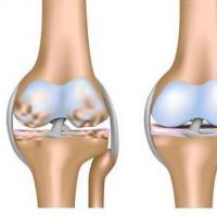 DOA of the knee joints: stages, symptoms and treatment
 Dimexide - detailed description and use at home Dimexide if it enters the stomach
 Andrey Stygar: How to make inventory profitable?
 Meaning of continued fractions in Collier's dictionary