Do-it-yourself plasterboard ceiling step by step instructions. How to assemble a suspended plasterboard ceiling with your own hands. Not to buy tools


More than ever before, people today need electricity, which is needed for almost everything from charging your phone to heating water. In order for the usual lifestyle not to be disturbed, high-quality wiring installation in the house is necessary. For its implementation, experience and rules of thumb accumulated by experts.

Electricity is a source of comfort
Safety Basics - Mistakes and How to Avoid Them
Ignorance or inattention to details can lead to installation errors. With further operation, such wiring in the house will cause malfunctions, damage to property, and sometimes a fire. There are simple rules that allow the master to act not at random, but according to safety rules:
- In a new building, before laying the wiring, a place is selected for the switchboard. It is installed close to the entrance, in a non-freezing room. When drawing up a shield diagram, it is reasonable to immediately think about the RCD (device protective shutdown), ground loop and other protective devices.

Mounted switchboard
- All work on the replacement of electrical wiring (in the old dwelling) must be carried out with the power turned off at the electrical panel. It is required to leave a warning sign on it to avoid an unpleasant surprise.
- Wiring in the house is preceded by drawing up detailed plan networks and electrical appliances.
- Even if all circuit breakers are turned off, before starting work, the presence or absence of voltage on the contacts or conductive surfaces is checked with an indicator screwdriver.

A warning sign must be hung on the introductory machine
The most common mistakes:
- Use of aluminum wires. According to the requirements of the PUE (rules for the installation of electrical equipment), in residential buildings it is allowed to use aluminum wires with a cross section of at least 16 mm². Wires of this diameter are usually used only in cables that carry current to the house, but not inside it. When replacing wiring, a combination of copper and aluminum parts is unacceptable - at the point of their connection, the contact will burn out over time due to contact resistance.
- Insufficient waterproofing. For long and safe operation of the system, care must be taken to carefully insulate all wires in rooms with high humidity. Poor-quality insulation most often finds itself in the bathroom, pantry, kitchen or terrace.
- Shtroba. A depth of 2-2.5 cm is considered optimal. Grooves with a shallower depth are difficult to plaster.

Chasing the wall for wiring
- Cable work. Diagonal laying is prohibited; the wire cross-section must be calculated according to the system parameters.
- distribution boxes. To avoid confusion and ease of maintenance, they are placed under the ceiling.
An example of drawing up a wiring diagram in a private house
The scheme of future electrical wiring is based on the plan of a private house. It consists of two parts, electrical and assembly. The main elements are outlined schematically, “for themselves”.
- Wiring diagram. The wiring diagram in a private house shows the method of including energy consumers in the circuit and their number.

Example electrical circuit wiring in country house
- Wiring diagram. Specifies where to mount devices. This data will help you calculate the number of cables and additional consumables needed.

Mounting version of the wiring diagram
The main elements of the network include wires, sockets, switches, meters, fuses and relays, junction boxes, in addition:
- entry point for external power cable;
- connection points for high power household appliances;
- ceiling and wall lighting fixtures.
The beginning of the power supply of the house is the electrical panel. A supply wire is supplied to it from the outside (more often through an overhead line), supplying a single-phase or three-phase current.
On our website you can find contacts of construction companies that offer electrical work services. You can directly communicate with representatives by visiting the exhibition of houses "Low-Rise Country".
Video description
An example of drawing up a plan for the location of electrical equipment on video:
To increase reliability, consumers are divided into groups on the shield (connection by groups of points):
- Lighting.
- Socket sockets.
- Power elements (boiler, electric stove, washing machine).
- Household groups (basement, garage).
Breakdown of consumers by rooms or floors is allowed. In this case, each group needs individual protection devices (automatic devices, RCDs).
Each room has a lighting and socket group, there are more of them in the kitchen (warm floor and electric stove are connected as a separate group). For powerful household appliances and lamp nodes of the circuit in the bathroom, grounding is provided (connection via a cable with an additional residential "ground").
Preparatory work for the electrical wiring device
So that wiring in a country house does not cause problems during operation, preparatory work and calculations. These include the calculation of the total power of the devices planned for installation; based on these numbers, the cable is selected.

The power of some household appliances
Power consumption calculation
The total power consumption is the sum of the individual capacities of household appliances, lighting elements and power equipment. These values are taken from special tables; they can be found in the technical data sheets of the devices.
To independently obtain the final power consumption of the devices, it is necessary to sum up the power of all consumers on this wire. It is known that at the same time all devices are not turned on. Therefore, the resulting amount is multiplied by the demand correction factor (simultaneous use factor). The coefficient is 0.8 (if the total power is less than or equal to 14 kW), 0.6 (up to 20 kW), 0.5 (up to 50 kW).
Example: if the resulting number is 32.8 kW, then the estimated power consumption is: 32.8 * 0.6 \u003d 19.68 kW.
By dividing the total power by the voltage (220 V), you can find out the maximum current. For example, if the power turned out to be 5 kW (5000 W), the current strength is 22.7 A.
Video description
A visual example of calculations in the video:
Choice of cable section by length and power
The cable cross section is selected according to the previously determined maximum load current and the conductor parameter (current density for this material). With a current strength of 22.7 A and a conductor density of 9 A / mm2 (copper), a conductor with a cross section (CPS): 22.7 / 9 \u003d 2.5 mm2 will be suitable.
Copper is considered best material due to its properties: wear resistance, high thermal and current conductivity (even during oxidation), ductility. Copper wire It lends itself well to twisting and withstands a load twice that of aluminum of the same section.

Calculation of the section according to the load (kitchen)
The optimal cross section for the socket group is considered to be 2-2.5 mm2, 1.3-1.5 mm2 will be sufficient for connecting lighting devices, for powerful electrical appliances it is better to play it safe - at least 4 mm2.
The length of the cable is calculated by taking measurements of all straight sections with the addition of an allowance of 10-15 cm on each side. The approximate length of the cable can be obtained by multiplying the area of \u200b\u200bthe premises by two.
The sequence of installation work
Installation work requires an integrated approach. They begin after the acquisition of the cable. Additionally, electrical accessories are purchased: sockets, socket boxes, switches, cable channels and junction boxes.

All materials must be prepared in advance.
Ground Loop Installation
Any private house must be equipped with a ground loop, which performs several tasks:
- Protects the inhabitants of the house when voltage appears on the device case.
- Supports the safe operation of appliances operating in a humid environment (washing and dishwashers, electric stove, boilers and instantaneous water heaters).
- Reduces the level of noise (interference) in the electrical network.
The circuit is mounted in the ground next to the house; inside, grounding is connected to the electrical panel. It is required for:
- high power electrical engineering;
- light sources (chain groups) in bathrooms.

Switchboard installation
Installation of switchboard elements
After the electricity connection scheme in a private house is selected, and the consumers are divided into groups, a switchboard is mounted. It contains:
- circuit breaker and RCD - common;
- automatic machines and RCDs - for selected groups;
- counter;
- neutral bus and main ground bus.
On the shield, the function of the core can be determined by the color of its insulation:
- white (sometimes red, black or brown) corresponds to the phase;
- blue - zero;
- yellow-green - protective earth.
The final switchboard for electrical wiring in a private house is assembled after the wiring is completed.

Applicable wire colors
Installation of electrical wiring of closed and open type
Wiring in a new house is laid in two ways - open and closed, and the first option is often chosen if the second cannot be used.
- Open wiring. It is laid over the walls and, if desired, protected by cable channels. It has its advantages - it is always available for inspection. At the same time, like any technical element in the interior, it hurts the eye. The exception is the design of rooms in the loft or retro style, where such solutions are welcome.
With open installation, the cable is fastened with brackets to the surface, then it is closed with a box. Recesses for sockets and switches are made with a puncher or drill.

Box (cable channel) for open wiring
- Hidden wiring. At concealed installation you have to ditch the walls (punch channels), lay the wires and hide them behind the wall trim. This method is more reliable and durable, but at the same time time-consuming and costly for future alterations. In order not to touch the cables when drilling walls in the future, it is worth stocking up on a network layout plan.
Electrical wiring in the house is done according to an invariable rule: laying is done strictly horizontally or vertically, any other way is not allowed. Bends are made at right angles.
Before installation, in accordance with the scheme, walls, horizontal and vertical sections are marked. This can be done using a laser level or a plumb line smeared with chalk or charcoal. You can take pictures of the walls with the markings applied. The memo will help in the future not to touch the wiring with a drill or a nail.

You need to draw a diagram of the location of the wires inside the walls
With hidden installation, strobes (grooves in the wall surface) are pierced with a chisel or grinder or a special chasing cutter. The wires are placed in strobes, they are fixed and masked with plaster or alabaster. Sometimes concealed wiring carried out not in the strobe, but under the plinth, which retains access and the possibility of verification.
Wiring in a wooden house
The organization of wiring in such a dwelling has its own characteristics. Internal wiring with wires buried in walls increases the risk of fire for wooden structures. Therefore, the open version is the safest.

Wiring in wooden house
It is preferable to use a flat cable; to prevent sagging, it is fixed with fasteners made of tin or plastic.
When the network is assembled and all elements are connected, the serviceability is checked.
Video description
For wiring errors in a wooden house, see the video:
Lead time and approximate cost of some works
Turnkey electrical installation in a cottage is completed in 4-6 days on average. Complex installation will cost 18-60 thousand rubles, replacement of wiring - 15-36 thousand rubles.
Electrical wiring on the floor of a private house will be carried out for 9-12 thousand rubles.
A comprehensive replacement of wiring in a wooden house will cost 18-29 thousand rubles.
Laying a cable with a cross section of up to 4 mm in a strobe - 25-30 rubles. for m/n.
Laying a cable with a cross section of more than 4 mm in a strobe - 42-55 rubles. m/n.
Chasing plaster walls - 75-85 rubles. for m / n, brick - 92-100 rubles. for m / n, concrete - 105-112 rubles. for m/n.
Electrical panel assembly (meter + 3 machines) - 980-1100 rubles.
Connecting an electric meter with installation (220 volts) - 665-720 rubles.
Connecting an electric meter (380 volts) - 1050-1130 rubles.

Loft-style interior with exposed ceiling wiring
General rules for connecting to the electrical network
Following the installation of electrical wiring, automatic machines, RCDs and electrical appliances are installed. To put into operation the electrical equipment of a private house, a specialist from the energy supervision, authorized to conduct acceptance tests, is invited.
After checking the safety of the electrical installation, a "Act of approval for connection" is issued, allowing the further use of the equipment. Based on this document, the energy supply organization concludes an agreement with the owner of the house and connects the dwelling to the support.
Video description
Clearly about the connection of electrical wiring in the video:
Conclusion
The life of a modern person is so dependent on electricity that even an hour without electricity seems to most to be endless. Things stop, the rhythm goes astray, plans remain unfulfilled. Faulty installation can lead not only to short-term malfunctions of the system.
Electrical malfunctions (caused by violation of the rules for the construction and operation of electrical equipment and household electrical appliances), according to the Russian Emergencies Ministry, caused 41,374 home fires in 2017. To protect your home and your loved ones, you should take care of many things in advance, but you should start with high-quality electrical wiring.
More recently, the load on the electrical network in residential premises was negligible. Calculations, installation of networks were not given due attention. Power supply projects were carried out according to standard schemes. Appearance modern technology high power causes the redevelopment of the entire network of electrical apartment wiring, its recalculation in terms of power and the replacement of electricians. To perform design and installation work in a new formation, you need to know modern principles arrangement of the electrical network of the residential premises.
Home electrical planning
So that during the operation of electronic equipment and connecting it from various electrical points does not lead to constant re-laying of network elements, so that you do not have to constantly ditch the walls of the apartment, experts recommend starting work on arranging the electrical network by drawing up a power supply scheme. An example of a wiring diagram and connection of electrical equipment can be seen in Figure 1.
Rice. 1. An example of an apartment power supply schemeSuch a drawing, a diagram is formed in the “reverse order”: initially, all used lighting equipment and power equipment are applied to the apartment plan; further, on the basis of power calculations, the wiring diagram of the conductors, the cross section of the wires, and protective devices are selected.
Power part
The power part of the electrical network includes powerful equipment used in the apartment: ovens, stoves, heating tanks, air conditioners. To connect them, separate powerful lines are allocated, protected by separate circuit breakers (RCD). This design method will allow safer operation of equipment in the apartment and more efficient repair work in electrical wiring networks.
lighting part
The next block of the electrical circuit of the apartment is the lighting part. There are two design options here:
- one group;
- several groups of lighting equipment.
The first type of circuit is used in small rooms equipped with a relatively small number of lighting devices. The second lighting circuit method is more common. An example of such a connection is shown in Figure 2.
 Rice. 2. Design scheme for several lighting groups in an apartment
 If in the room, in addition to lighting elements, there is a need to use power supplies, transformers, they are also recommended to be turned on by a separate electrical circuit with a separate RCD.
Large home appliances
In any apartment, a place where a large number of household appliances, this is the kitchen. Most of them continue to work when the person does not directly use them. This is a refrigerator, electric stove, bread machine, and more. For the correct operation of the equipment and the constant protection of the network from overloads and short circuits, experts recommend that a separate line be allocated when developing the electrical circuit of the apartment. Such connections are made by laying electrical wiring of an increased cross section and installing an RCD with a high degree of load.
Drawing up a wiring diagram
Electrical wiring in an apartment begins with drawing up a network wiring plan. Installation of electrical wiring according to the existing design drawing is much easier and more expedient for a number of advantages:
- the power grid scheme will allow you to plan in advance necessary equipment and means;
- the presence of a circuit will allow you to accurately determine the power of the input input;
- the drawing gives an understanding to the installation personnel about potentially fire hazardous wiring nodes in order to take measures to re-plan them or take additional safety measures;
- the scheme will allow you to perform the installation on a planned basis, with verification of the completion of the full cycle.
Examples of schemes for a one-room apartment
Electrical engineers believe that if the total load on the apartment's electrical network does not exceed 25 A, then it is possible and even cost-effective to plan the network with one circuit per machine. This method is a typical typical scheme of the past, when lighting elements with were included in the circuit. Today, these methods have been abandoned and installation is carried out along independent separate circuits. An example of wiring a one-room apartment is shown in Figure 3.
 Rice. 3. Power supply scheme for a one-room apartment
 The drawing shows a competent distribution of the load of the network of a one-room apartment into several separate circuits with their own RCDs. Such a system will ensure trouble-free operation and correct operation of the equipment without a voltage drop.
For a two-room apartment
The difference between the drawing for the installation of supplies two-room apartment from a one-room apartment it consists in more circuits in terms of wiring. Some arrangements are possible here. Figure 4 shows an example of such a circuit.
 Rice. 4. Power supply scheme for a two-room apartment
 The example clearly shows several lighting circuits, as well as separately allocated protected circuits for the kitchen, rooms and other powerful equipment.
For a three-room apartment
Figure 5 shows an example of a drawing that is often used for apartments with three or more rooms, where a fairly large number of conductors will come out of one switchboard.
 Figure 5. An example of a power supply scheme for a three-room apartment
 The peculiarity of this option is separate circuits enclosed in separate blocks with their own protection. In this example, 2 blocks (25 A and 40 A respectively). This method allows you to separate the zones of cable products, makes the system more convenient and practical.
Choice of laying method: open or hidden
After determining the layout of the cable lines, the method of laying the cables should be adopted. There are two ways to lay lines - hidden, open.
The first method is common when the decoration of the premises is carried out with suspended structures and false panels (drywall, MDF). There is no need to make grooves (strobes) in the walls with subsequent puttying. Hidden wiring, made in the apartment, has a number of significant advantages:
- preservation general view, the integrity of the interior;
- less stringent requirements for cable installation conditions;
- increased tolerances for permitted currents.
It is not uncommon to meet the option of open wiring. Wires are often placed in special plastic boxes attached to decorative trim room surfaces. An open cable laying method has the following advantages:
- the possibility of installation after or during finishing work;
- faster installation;
- the possibility of upgrading the network by laying additional cables or dismantling them.
At present, if the arrangement of the electrical network is integral part general repair premises, experts often use the hidden method of laying conductors.
The tool you need to get the job done
Installation, repair of electricians is a complex, time-consuming process, performed by professional electricians. You can't do without a set of special equipment. In work (for laying, replacing old electrical wiring), the installation team uses the following a set of professional tools and accessories:
- angle grinder with cutting wheels for stone;
- bit;
- perforator;
- screwdrivers with handles made of insulating material;
- phase indicator (indicator);
- wire cutters;
- pliers;
- extension;
- level;
- putty knife;
- portable lamp.
List of further works
After the drawing of the wiring diagram is outlined, they begin to calculate the parameters of the network and its installation.
Cable selection and calculation of its cross section
For an accurate calculation of the cable cross-section according to the power of consumers, the following relationship is used: I \u003d P / U, where P is the total power of all consumers in the circuit, for which the cross-sectional area of \u200b\u200bthe conductor cores is chosen, and U is the voltage of the apartment network. Most often, the wiring circuits are built in such a way that the electric current load in them does not exceed 25 A. In this case, the following sections are used:
- wire VVG-3 * 2.5 - a two-core power cable with a cross section of one conductor 2.5 mm 2. This is the most used wire for organizing the electrical network in the apartment. They connect the switchboard to the junction boxes of the premises;
- wire VVG-3 * 1.5 - a two-core power cable with a cross section of one conductor 1.5 mm 2. Such conductors are mounted from junction boxes to sockets,;
- wire VVG-3 * 4 - a three-core power cable with a conductor cross section of 4 mm 2. Such conductors are separated into separate circuits for connecting powerful consumers of apartments (stove, heating tank, etc.).
Marking sockets and switches
The placement of sockets and switches in the apartment should ensure the convenience of their use and cover the needs of residents in connecting equipment. A typical example of the layout of electrical equipment (connection points) is shown in Figure 6.

When marking the locations of sockets, switches, the following requirements of modern standards must be observed:
- sockets and switches are located to the left of the doors;
- switches are mounted at a height of 0.9 m from the floor;
- in living rooms, sockets are located at a height of 0.4 m from the floor, in the kitchen - 0.95 -1.15 m, in the bathroom the use of sockets is prohibited.
wall chasing
After marking the placement of junction boxes, sockets, switches, installation points for fixtures, they begin to arrange grooves (strobes) along the walls, on the ceiling for wiring. It is worth remembering that chasing should be carried out in a horizontal and vertical planes along straight lines. This in the future will allow to more accurately determine the location of the wire. The grooves are made using a grinder or a puncher. The depth of the strobe must be at least 20 mm, and the width must be sufficient for laying all the cables planned for laying in this place.
Cabling
The principles of laying cables for hidden and open wiring are the same. Installation starts from the connection points and leads to the switchboard. Next, the line is brought into the shield, go to another circuit. If necessary, identification tags are hung on the final sections of the wiring for a quick reference. After the installation is completed, the cables are covered with boxes or puttied in the wall.
Installation of sockets and junction boxes
The laid wiring is brought to the mounted junction boxes and socket boxes, wound up in them, the ends are driven out with a small margin. All wiring branches are arranged in boxes. The connection of conductors of aluminum or copper wiring must be reliable. For connection, it is advisable to use special devices, as shown in Figure 7.

Immediately before connecting the wires, they ring and make sure that they are connected correctly. installation work at this stage.
Installation and assembly of the electrical panel
When all the cables of all electrical circuits are laid to the installation site of the electrical panel, they begin to organize the switchboard of the apartment. This part of the electrical network is characterized by a large number of conductors, protective devices, so it is very important to make all connections correctly. For the shield, always choose mounting boxes with a certain margin of seats. This will allow future upgrades or troubleshooting of the system.
An example of an electrical panel diagram for a standard apartment is shown in Figure 8.
 Figure 8. An example of a switchboard diagram
 In the figure, the positions indicate: 1 - introductory machine; 2 - electric meter; 3 - zero bus; 4 - protective ground bus; 5–9 - automata; 10 - a separate machine for lighting
Installation of sockets and switches
In advance mounted boxes with the output ends of the wiring, sockets are mounted,. The process is not difficult and will require a minimum set of tools: pliers, wire cutters, a screwdriver. This The final stage installation work of the electrical network of the apartment.
Checking the quality of work
The quality of the work performed is checked by turning on the wiring circuits and checking for the presence of voltage, the correct distribution of phases in the network. This procedure carried out using voltage indicators. Incorrect installation can also immediately show a disconnected circuit breaker from a short circuit.
Useful video on the topic
More recently, the wiring in a private house was made of an aluminum cable with a cross section of 2.5 mm². And that was more than enough to connect a refrigerator, iron or radio.
However, time does not stand for less, and every day the number of household appliances in the house only increases (air conditioners, electric stoves and ovens, boilers, autonomous heating boilers, and so on). In this regard, the load on the electrical wiring increases significantly, which can lead to its failure, followed by a short circuit or even fire.
For this reason, when new construction or implementation repair work, first of all, it is necessary to carry out a new installation of electrical wiring in a private house. To do this, you can either order the services of professionals, or you can do all the work yourself.
In the second case, it will be extremely useful to read this article, since it will describe in detail each of the stages of electrical installation and present all the basic requirements, recommendations and restrictions when performing this type of work.
The main stages of installation of electrical wiring in a private or country house

According to many years of experience in the performance of electrical work, all work can be divided into the following stages:
- Drawing up a power supply scheme (number and location of sockets, switches, lamps, and so on).
- Determination of the installation location of the switchboard.
- Marking ceilings, walls and floors for laying cable and wire products and installing socket boxes and junction boxes.
- Chasing walls for hidden electrical wiring.
- Chasing walls for the installation of a switchboard (when installing an internal shield).
- Drilling holes for the installation of sockets and junction boxes.
- Installation of routes for fastening the corrugation (if the laying of cable and wire products will be carried out in the corrugation).
- Laying of cable and wire products.
- Installation of socket boxes and rough embedding of strobes.
- Disconnection of junction boxes.
- Installation of the ground loop.
- Checking the grounding resistance of the mounted circuit.
- Assembly and installation of the shield.
- Check the functionality of all sockets and switches.
- Installation and connection of sockets, switches and lighting fixtures.
Let us consider in more detail the main stages, in order for the installation of electrical wiring in the house to be carried out efficiently and last at least 20–25 years (this is exactly the minimum service life of copper wiring).
Drawing up a power supply scheme (project for the arrangement of sockets and switches)
During construction or overhaul, the first stage is the development of design estimates. This should be done by specialized organizations with a license. In this article, this option will not be considered, since the purpose of this article is to present detailed description do-it-yourself electrical installation.
In our case, the project (power supply scheme) implies determining the installation locations for sockets, switches, household appliances, lighting devices, a lighting panel and the method of laying wires (hidden or open). Consider what are the main recommendations when developing a power supply plan.
Basic recommendations when drawing up a power supply scheme for a private house

- All cable and wire products, regardless of the installation option, must be carried out strictly vertically or horizontally.
- Cable turns must be strictly 90°.
- Minimum distance from cables to portals, window and doorways should not be less than 10-15 cm.
- The optimal distance from the level of the finished floor to the switches should be 90 cm (in accordance with European standards).
- The optimal height of the outlet groups is 30 cm from the level of the finished floor (with the exception of outlets on working surface in the kitchen, in the bathroom for connecting a hair dryer, a razor, a boiler, and so on).
- Sockets are recommended to be placed on both sides of the bed or sofa.
- In places where TVs are installed, the number of sockets must be at least 4 pcs (2 pcs for the Internet and a TV cable and 2 for connecting a TV and a tuner).
- For large corridors and rooms, it is recommended to use walk-through switches.
- All powerful consumers (air conditioners, electric furnaces and ovens, boilers, heating boilers, etc.) must be connected exclusively from a switchboard with separately installed protection.
- The optimal installation height of the switchboard is 1.5–1.7 m from the level of the finished floor.
- It is forbidden to lay cable and wire products closer than 20 cm to the gas pipe.
- All metal elements and sockets must be grounded.
What is the usual wiring diagram in a private house

Of course, houses can be very different from each other, but the essence of high-quality installation is approximately the same for everyone, and it is as follows:
- An electric meter is installed on the facade of the building, to which a descent from the overhead line is carried out by means of a wire (the power supply organization is responsible for this part and for the meter).
- In a garage or some other room, a voltage stabilizer (s) and a power distribution panel or automation are installed, which controls and transmits electricity through an incoming copper cable with a cross section of 10–35 mm².
- On the street near the premises where the switchboard is located, a generator is installed that supplies the house in the absence of a centralized power supply.
- A separate switchboard is installed on each floor inside the house, to which the input cable is connected in parallel.
- Separate RCDs are installed in the switchboard for the sockets of each of the rooms, circuit breakers separately for each room and separate RCDs for air conditioners, boilers, heating boilers and underfloor heating systems.
- All powerful consumers are powered strictly from the switchboard, which provides for the installation of individual protection elements (RCD).
- A separate junction box should be installed in each room, in which the input cables, and cable and wire products of the socket group and lighting circuits will then be switched.
Important! When drawing up a power supply plan, it is necessary to take into account the type of supply network. If you have a 3-phase network, then the input cable to the house should have 5 mils, in the case of single-phase power, the number of cores of the supply cable should be 3.
After you have decided on the power supply scheme and the installation locations of electrical accessories, you can start marking the room.

In order to perform the layout of the room you will need:

Initially, with the help of a laser level (water level) and a tape measure, we mark the installation locations of sockets and switches. Further, using a building level or a laser level and a pencil (beats), we mark, using strictly horizontal lines, the descents from the ceiling to sockets and switches for subsequent gating.
Using a laser level, we mark on the ceiling the places for laying cable and wire products for the subsequent installation of fasteners for corrugations and cable laying.
We mark the installation location of the junction box, which should be chosen in such a way that the cost of cable and wire products is minimal.
Important! When marking the ceiling, keep in mind that all cables from sockets and switches and input cables to socket groups and lighting circuits will be brought into the junction box, so when installing corrugation mounts, you need to calculate how many cables will go where.

After marking, when performing hidden wiring, you can start chasing the walls. To do this, you will need either an angle grinder (grinder) or a wall chaser with a vacuum cleaner (for dust-free chasing):

Initially, you need to determine the depth of the strobe. Suppose you are mounting a cable in a corrugation with a diameter of 16 mm. In this case, the depth and width of the strobe must be at least 20 mm. The strobes are cut according to a pre-made markup.
Important! It is forbidden to make strobes at an angle or to strobe load-bearing structures (crossbars, bearing walls, floor slabs, etc.).
Also, at the stage of wall chasing, it is necessary to make a hole for the installation of an internal switchboard. Its dimensions depend on the number of modules. In most cases, a switchboard for 24–36 modules should be installed on each floor (depending on the number of rooms and the number of household appliances).
Drilling holes for sockets and junction boxes

For this we need:

To drill holes, turn on the “drilling + drilling” mode, insert the necessary bit and drill the required number of holes in pre-marked places.
Important! When installing several sockets side by side, it is necessary to buy connecting junction boxes, apply them to the installation site, and only then drill holes. Since otherwise you will not be able to install sockets with overlays that are installed under one bar.
Installation of cable and wire products

In most cases, when quality installation all cable and wire products are laid in the corrugation. This provides additional cable protection, simplifies installation and makes possible subsequent replacement in case of cable failure without opening the walls and violating the repair. It is also worth noting that do-it-yourself wiring in a house in 90% of cases is done in a hidden way (in strobes) and very rarely in cable channels in an open way.
What type of cable and wire products to choose

Here, of course, you need to perform a lot of calculations, but based on many years of experience, I would like to note:
- To power the lighting circuits, a cable 3x1.5 mm² (PVSng, VVGng ShVVPng) is required.
- To power the socket group of each of the rooms, a 3x2.5 mm² cable.
- To power household air conditioners, the cable is 3x2.5 mm², but if its power is more than 5 kW, then the cable cross-section must be increased to 4 mm².
- For powering the electric stove and oven the cross section of the cable must be at least 4 mm².
- To power heating boilers (electric), depending on the type of power supply (single-phase or three-phase), the cable must be from 4 mm2 to 35 mm2 (depending on power). In most cases, the manufacturer writes the recommended cross section and number of cable cores.
Important! When laying cable and wire products, each outlet group must be connected to a separate RCD (namely, RCD according to the requirements of SNiP). Also from individual machines must be connected:
- electric floor heating systems;
- boilers;
- washing machines;
- electric stationary heaters;
- heating boilers;
- air conditioners;
- dishwashers.
What should be the input cable
The input cable from the meter to the house must be calculated according to the nominal value of the input machine (installed after the meter). But in most cases, an input cable with a cross section of 10–16 mm2 is sufficient for a 3-phase network and 16–70 mm2 for a 1-phase supply network.
Installation and disconnection of the junction box

After installation of cable and wire products, you can mount junction boxes in pre-cut holes. For their reliable fixation, it is necessary to use alabaster, which seizes very quickly, after which you can disconnect.
Disconnection is performed in 3 ways:

Important! Wiring in the junction box is best done using cable color coding (blue to blue, brown to brown, yellow-green to yellow-green). This will allow you not to confuse the phase with earth or ground. In this case, the brown (white) wire is the phase, the blue (black) wire is zero, and the yellow-green wire is ground.
Mounting and assembly of the switchboard

After laying the cable and wire products, installing and connecting the junction boxes, you can proceed with the installation of the electrical distribution panel.
How many modules do you need to install the shield

Wiring in a private house involves the installation of a shield on each floor in private houses, cottages or summer cottages. However, in order to find out how many modules you need, you first need to calculate how many consumers there will be. Let's do the calculation for standard variant that, using his example, they were able to do the installation of electrical wiring in the house with their own hands.
Let's say on your floor:
- 3 rooms.
- Kitchen;
- Corridor;
- Boiler;
- Washing machine;
- Underfloor heating system in 3 rooms and kitchen;
- Electric stove;
- 4 air conditioners.
Based on this, in the switchboard you need to install:
- 5 single-pole automatic switches for 10 A (lighting of 3 rooms, kitchen and corridor);
- 14 RCDs for 16 A (3 sockets in the rooms, 1 kitchen socket, 1 corridor socket, 1 boiler socket, 1 washing machine socket, 3 underfloor heating system, 4 air conditioners);
- 1 RCD for 25–32 A for connecting an electric stove.
From the above calculations, the number of occupied modules will be 35 pieces (30 modules occupy 15 RCDs and 5 circuit breakers). That is, we will need a switchboard for 36 modules. However, if you still want to connect a voltage limiter or the number of consumers is greater, then the shield must be mounted on 48 modules.
After mounting the switchboard, RCDs and circuit breakers can be mounted. They are easily mounted on a special DIN rail, which comes as standard with a shield.
Important! When the switchboard is turned off, the phase (brown) wires must go through automatic machines or RCDs, the zero (blue) wires must be collected on the zero bus and the yellow-green wires must also be connected on the 2nd zero bus).
Conclusion
Whether it's electrical wiring country house, or a cottage, when properly installed, will allow you to safely operate household appliances without worrying that a short circuit or fire may occur.
It is also worth noting that when the wiring in a country house is fully installed and connected to the ground loop, it is necessary to test with a megger and a device to test the resistance of the ground loop.
This article "Do-it-yourself wiring (wiring) in a private house: step by step description” will allow you to do the wiring yourself, but it is always better to entrust this matter to professionals.
Related videos
Electrical wiring in an apartment is one of the main stages of repair and construction work, which allows you to ensure reliable and uninterrupted power supply to the entire premises in accordance with the current requirements of PUE, PTB and PTEEP.
Since not only your personal safety, but also the safety of your property depends on the quality of the wiring in the apartment with your own hands, it is better to entrust this service to a highly specialized electrical installation organization with many years of experience. If you think that you can handle this case on your own, we recommend that you read this article in its entirety, which will describe in detail:
- Type of cable and wire products for each task.
- Recommended distance to sockets and switches from the floor.
- Number of circuit breakers or residual current devices for consumer protection.
- The nuances of chasing walls.
- The method of laying cable and wire products.
- Recommended number of sockets in each room.
- The best manufacturers of electrical products and much, much more.
What is the best way to start electrical work in the apartment

As a rule, an electrician in an apartment begins with the planning stage. What does it mean? In order to correctly replace the wiring, stretching new wires is not enough. First of all, it is necessary to determine the installation locations for sockets, switches, household appliances, and so on.
If you do not properly arrange communications, it will be very unpleasant when, after the completion of construction or repair and finishing work, some sockets will be located behind cabinets or a bed, and switches will be located either too high or too low.
Of course, in such situations, there is a way out! This is the connection of extension cords, but a natural question arises - why did you need to replace the wiring if you constantly stumble over them?
The first thing to do before starting repairs is to develop a plan or order a design project. In this plan, you need to draw where you plan to place cabinets, sofas, armchairs, beds, cabinets, household appliances, and so on.
Basic rules for a good plan

- All sockets must be located at a height of 30 cm from the finished floor.
- Switches must be located no lower than 90 cm from the floor.
- Sockets above the work surface in the kitchen are located at a height of 80-100 cm from the floor.
- On the working surface, at least 4-5 sockets are needed to connect household appliances (combines, mixers, blenders, and so on).
- In the kitchen, it is necessary to additionally provide sockets for the hood, refrigerator, washing machine, gas or electric stove, hood, underfloor heating (if any).
- In the bathroom, near the mirror, it is recommended to install 2-3 sealed sockets for connecting a hair dryer, electric razor, epilator, and so on.
- Also in the bathroom, it is necessary to provide sockets for connecting a boiler, underfloor heating, a washing machine, water filters.
- In places where a TV will be installed (living room, bedroom, nursery, and so on), it is recommended to mount 4–5 sockets, 2–3 of which will supply equipment (TV, tuner, game consoles, and so on) 1 will be used to connect the “Internet” cable ” and 1 more for connecting the antenna cable.
- Sockets in the bedroom should be placed on 2 pieces on each side of the bed for the convenience of connecting charging a mobile TV or lamp on the nightstand.
- Also in the bedrooms, it is recommended to mount a sconce with a switch near the socket on each side of the bed to create convenience when reading books.
- Switches are best located on the right side of the door if you are right-handed and on the left if you are left-handed.
And so with the plan for arranging sockets and switches they went broke. What to do next? Next, we need to choose the type of protection.
Selecting the type of protection
According to modern electrical safety requirements, each installation of electrical wiring in an apartment must be carried out in such a way that each wire in the electrical panel is protected by a separate machine or RCD (we'll talk about this a little later). What does it mean? Let's look at a specific example.
An example of protection calculation for a one-room apartment

Let's say you have a wiring diagram in one-room apartment. According to this scheme:
- In the room: 5 sockets for TV, 4 sockets (2 each) near the bed, 1 switch and 1 air conditioner.
- In the kitchen: 1 electric stove, 1 air conditioner, 4 sockets on the work surface, 1 socket for extractor hood, 4 sockets for TV (2 electric and 2 for internet and antenna) and 1 socket for the refrigerator and 1 switch (two-gang or one-gang).
- In the bathroom: 2 outlets near the washbasin, 1 outlet for a washing machine, 1 outlet for a boiler, 1 outlet (or rather, just a phase and zero) for underfloor heating and 1 switch.
- In the corridor: one socket and 2 walk-through switches.
According to the requirements of DBN and PTEEP, each cable must have its own protection using RCDs (sometimes they are replaced by circuit breakers). Based on these standards, the following number of RCDs (AB) should be installed in the electrical panel:
- In the room: 2 16 A RCDs, one of which will protect the air conditioner, and the second socket group and one 10 A circuit breaker to protect the lighting circuits.
- In the kitchen: one RCD for 16–32 A (depending on the power of the consumer) to protect the electric stove and oven, one RCD for 16 A for the socket group, one RCD for air conditioning, one circuit breaker for 10 A for lighting circuits.
- In the bathroom: one RCD for a washing machine, one RCD for a boiler, one RCD for a socket group, one RCD for underfloor heating, one AB for lighting circuits.
- In the corridor: one RCD for the socket group and 1 AB for lighting circuits.
Based on the above calculations, we will need an electrical panel for 24 modules, 20 of which will be occupied by an RCD and 4 AV lighting (if the introductory machine is installed in a switchboard on flight of stairs and surge protection (Barrier, ZUBR, and so on) will not be installed in the electrical panel. If the input AB and overvoltage protection will be mounted in this shield, then it should be for 36 modules (7 modules will be redundant).
What is the difference between RCD (residual current device) and AB (circuit breaker)

The main difference between these devices is the way they operate. What does it mean? In order not to consider in detail the principle of operation and characteristics of each of the devices, I would like to say one thing: circuit breakers work only in the event of a short circuit in the controlled section of the electrical wiring, and RCDs work when the wire insulation is broken or a leakage current occurs on the metal case of various household equipment.
To be more clear, the residual current device serves to protect a person from injury. electric shock, and AB simply protect household equipment.
Why is it worth connecting a washing machine and a boiler to a separate RCD

Since the main consumer of electricity both in the boiler and in washing machine- this is an electric heating element that comes into contact with water, sooner or later it will break through to the body, and if it is not powered from a separate RCD, then the light in the entire apartment will go out.
Selection of cable and wire products

According to the requirements of the regulatory documentation DBN, PTEEP, PUE and PTB:
- For powering socket groups, boiler, washing machine, air conditioner, hoods, it is necessary to mount the cable VVGng 3x2.5 mm or PVSng 3x2.5 mm.
- To connect the electric stove and oven, you need a cable VVGng 3x4 mm or PVSng 3x4 mm.
- For lighting circuits, VVGng 3x1.5 mm or PVSng 3x1.5 mm will suffice.
- If the wiring in Khrushchev is being replaced, the input cable from the power switchboard on the flight of stairs to the electrical switchboard of the apartment must be made with a VVGng (PVSng) 3x4 cable, provided that you do not have an electric stove, or with a VVGng (PVSng) 3x6 cable if installed in the kitchen oven or electric stove.
What is the difference between PVSng and VVGng
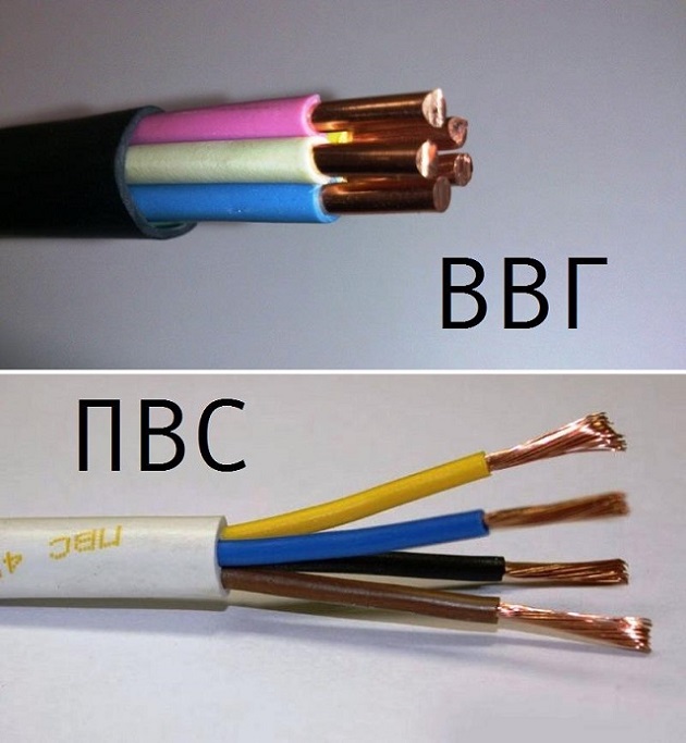
The only difference between these brands is the way they are made. The VVGng cable (for example, 3x2.5 mm) consists of 3 monolithic conductors with a cross section of 2.5 mm, and the PVA cable consists of 3 conductors, which are woven from many small copper wires.
What does the marking "ng" mean in the name of the cable
The prefix "ng" means that the cable does not support combustion. Thus, if a short circuit occurs in the electrical wiring, it will go out by itself, thereby protecting your apartment from fire.
How to install cable and wire products (electric cables)

- If a short circuit occurs in the wiring, you can replace the damaged cable without dismantling the finish, since it will be easy to get the cable out of the corrugation and replace it with a new one.
- If the electrical wiring in the apartment is made in the corrugation, then the cable has additional protection, and even if you are flooded by the neighbors, the electrical wiring will remain undamaged because the corrugation is airtight.
- When pulling the cable through the metal profiles on which the drywall is attached, only the corrugation can be damaged, and the protective sheath of the cable will become undamaged.
How to unplug electrical wiring in separate rooms

Consider an example when wiring is done in an apartment with your own hands. Suppose you have already assembled an electrical panel and run cables from it to the rooms. However, what to do next if 2 or 3 cables come into the room (lighting, sockets and air conditioning), and 3-6 cables come out of the sockets (depending on the number of sockets)?
To do this, you need to install a junction box. In this electrical product, all cables are interconnected by welding, soldering or special clamps (for example, WAGO).

Important! If you connect a socket group, then according to the marking and correct switching in the electrical cabinet, the brown wire is the phase, the blue wire is the common zero, and the green and yellow wire is the ground.
What is forbidden to do when replacing the wiring in the apartment
- Connect wires outside distribution wiring.
- Connect the wires by means of twists (because over time the contact in the twists will deteriorate and a fire may occur).
- Break the seals from the electricity meter (if it is installed inside the apartment).
- Ditch the walls in panel houses. It is allowed to make only vertical strobes in the plaster layer or to lay electrical wiring in the corrugation behind a false plasterboard wall.
- Repair the electrical wiring in the apartment using a truncated cable (TU marking). For example, if it is written on a cable with the TU mark that the cable cross section is 3x2.5 mm, then in reality it can be the cross section can be in the range of 1.5–1.8 mm.
- Mount cable and wire products closer than 10–15 cm to window and door openings.
- Use non-waterproof equipment in bathrooms. For installation in bathrooms, the degree of protection of sockets must be at least IP54.
- Install electrical wiring near a gas pipeline or water supply pipes.
- Connect to AB 16 A cables with a cross section of less than 2.5 mm², as the cable will heat up and lose insulation, and the circuit breaker will not work.
- Make horizontal grooves.
- Connect equipment directly without any protection (AV, RCD, and so on).
- Violate the integrity of the structure of the bearing wall.
conclusions
Replacing electrical wiring in Khrushchev is a responsible process that requires certain skills and knowledge, since the safety of not only you and your family, but also all household equipment and appliances depends on the quality of its implementation. And if you want the wiring in a one-room apartment to last at least 20-25 years, then it is better to entrust this business to trusted electrical installation organizations.
Related videos
 Hairpin interpretation of the dream book Why dream of buying a hairpin
 Win competitions Why dream of acrobatic competitions
 Dream interpretation sparrow looks out the window
 Divination by Tarot Etteila - Horoscope of Life Collection of free divinations
 The meaning of tarot cards in divination
 What does it mean to see yourself from the side in a dream?
 Social movements and their types