Tube how many wires through a wooden wall. The device of passages through walls, crossings of postings. Basic requirements for the implementation of fire-resistant seals
Passages through internal and external walls, partitions and intermediate floors should be made in a pipe or opening, which would make it possible to replace the electrical wiring. The passages of unarmoured cables and wires through fireproof walls and interfloor ceilings should be carried out in metal or insulating semi-solid rubber, polyvinyl chloride tubes (uncut) or in segments of plastic pipes, and through combustible walls - in insulating tubes enclosed in steel segments. ends metal pipes be sure to end with bushings or funnels. The installation of insulating tubes is necessary not only to ensure the replacement of wiring, but also to strengthen the insulation of unprotected wires.
Wires with a folded seam (APRF, PRF, PRFl) are allowed to be laid through wooden walls without additional protection.
Passages can be open and closed. Open passages of wires and cables are carried out in buildings with wooden walls and ceilings. In a brick building, the passage can be made hidden, in a furrow carved into the wall, but not under a layer of plaster.
When preparing passages through walls and ceilings, it is necessary to take into account the environment of the adjoining premises. If the adjoining premises are classified as dry, then the wire in the wall is laid through one hole. When passing from a dry room to a damp, damp or outside, from damp to damp, each wire must be pulled in a separate insulating pipe.
To ensure the flow of water, the holes are made with a slight slope towards a damp, damp room or outside. From the side of the dry room, the hole is framed with an insulating porcelain or plastic sleeve, and from the side of the wet, damp or outside - with a porcelain funnel. Bushings and funnels are smeared with alabaster or cement mortar so that the collar of the bushing lies tightly on the wall surface, and the outlet of the funnel completely comes out of the wall and is directed downwards. The bushings are put on the insulating tube.
The connection of wires when leaving a dry, damp room to a damp or outside building should be carried out in a dry or damp room at the roller or in a junction box installed at the aisle.
To prevent the penetration of water, the spread of fire, open passages of cables and wires through the outer walls of the premises should be sealed with easily removable fireproof materials (mineral wool, slag, etc.) after laying the electrical wiring. Funnels on both sides are filled with an insulating compound, such as bituminous mass. Open passages through internal walls normal non-explosive and non-flammable premises may not be compacted.
Open passages of wires through interfloor ceilings are made in an insulating tube with protection against mechanical damage to a height of at least 1.5 m. When wires are laid hidden through interfloor ceilings, wires are passed in insulating tubes, the exits of which are terminated with porcelain funnels.
When making passes through interfloor ceilings, where protection of the wire from mechanical damage is required when it exits to the upper floor, it is forbidden to use wires of the PRD, PRHD brands (in steel pipes these wires are not laid).
When making a passage through an interfloor ceiling, single-core insulated wires of the APR, APV, APRV, etc. brands are used. Insulated pipes in the passages should not have breaks along the length and are sealed with the outer edges of the bushings and funnels (they can protrude from them by 4-5 mm ). It is forbidden to make passages in wooden walls at the joints between logs.
Intersections of wires and cables are not recommended. In open electrical wiring, when crossing unprotected wires with unprotected or protected insulated wires (with a distance between them of less than 10 mm), additional insulation must be applied to the unprotected wire: a piece of a whole PVC tube is put on it or 3-4 layers of insulating tape are applied.
In brick buildings, wire crossings are carried out hidden in plastered furrows - twisted two-core wires of one of the intersected lines are laid in a furrow, putting an insulating or PVC tube on them. At the points of entry and exit of the wire from the groove, porcelain funnels are put on the insulating tube.

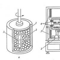
Rice. Pipeline bypass:
1 - wire; 2 - rubber tube; 3 - funnel.
In cases where wiring is carried out with single-core wires, each of them is placed in a separate insulating tube.
Around metal structures buildings, beams, pipes and especially pipelines with hot liquids, condensation and rust can form, which destroy the insulation. Therefore, when crossing protected and unprotected wires and cables with pipelines (Fig. 38), the distance between them must be at least 50 mm, or wires and cables at the intersection must be laid in insulating or metal pipes embedded in the furrow. If the distance from wires and cables to pipelines is less than 250 mm, they should be additionally protected from mechanical damage at a length of at least 250 mm in each direction from the pipeline.
With open parallel laying, the distance of wires and cables, as well as the distance from the hidden laying junction boxes to pipelines, must be at least 100 mm.
When crossing with hot pipelines, wires and cables must be protected from high temperatures
Cable passages through walls and ceilings. The places where cables pass through ceilings, walls, fire-resistant partitions in cable tunnels must be carefully sealed with non-combustible material, while sealing is also performed around the cables passing through the nozzles. This is one of the necessary measures to prevent the spread of fires in cable networks and the penetration of water into the building through pipes.
Normalized distances. The PUE defines the smallest allowable distances between the cable being laid and other cables, building foundations, green spaces, pipelines with flammable liquid, heat pipes, communication cables, electrified and non-electrified railways, tram rails, both when they are parallel and at intersections with them . The PUE also provides for protection measures when approaching these devices.
These limits are set in order to create normal conditions for the operation of cables and minimize the harmful effects of any kind of devices on the cable. If we are talking about pipelines, then the minimum allowable convergence during parallel laying of 1 m is necessary so that the cable is not damaged during excavations related to the repair of the pipeline. For the heat pipe, the specified convergence is 2 m to minimize the detrimental effect of the heat generated by the heat pipe on the cooling conditions of the cable. Tram, electrified railways, subway lines are a source of propagation of stray currents in the ground, which, in the absence of proper protection, have a destructive effect on the armor and metal sheath of the cable. Therefore, the permissible approach to such structures is already 10 m, or, if this distance needs to be reduced, the cables are laid in insulating pipes (for example, asbestos-cement, impregnated with tar or bitumen). Thus, each approach and intersection restriction has its own justification and must be observed when laying cables.
Industrial preparation of cables. Recently, a method has been developed and implemented in a number of installation organizations of the method of preliminary preparation of measured lengths of armored cables in workshops. On the technological mechanized line, the cable is rewound from the factory drum to a special inventory drum with the required length measured on the cable meter; cable cutting and installation of terminations and couplings. The prepared sections of cables are tested with increased voltage, the cable cores are marked and colored, and the cable in the inventory drum is delivered to the facility for laying on the prepared route.
The main element of the technological line is an inventory cable drum with an electric drive, as well as a counting device, with the help of which the process of measuring and rewinding cables is mechanized. The inventory drum consists of a welded frame, inside of which a rotating drum is placed. On the side cheeks of the rotating drum, structures are provided for fastening couplings and end fittings. The electric drive is connected to the drum by a hinged shaft. Measuring device with a counter type SK-1 consists of a frame and a movable stand. Guide rollers and a copper disk connected to the cable meter are installed on the frame. The measuring disc, moving transversely on the guide studs, ensures the laying of the cable coil to coil. The lifting of the drum with the cable is carried out with a cable jack. Other assembly operations are also mechanized at the stand: rounding of sector cores, crimping of lugs and sleeves (PGEP press), welding and soldering with propane-butane torches, cable cutting with a stationary cable knife with manual drive, marking plastic tags with a special device, etc.
Industrial harvesting of cables reduces cable waste and overall labor costs, reduces installation time and improves the quality of installation of cable glands and terminations.
When laying any communications, cable penetrations must be constructed - products, prefabricated structures that are designed for the passage of cables, pipelines, communication lines through walls and partitions. Their main purpose is to prevent the spread of fire to neighboring rooms through flammable materials. They are arranged on the basis of SP 2.13130.2009 and GOST R 53310-2009. Their installation is mandatory and regulated by Federal Laws.
Fire compartments and cable penetrations
According to the requirements, during the construction of residential buildings, they are divided into fire compartments, which block fire and smoke on their territory and prevent them from spreading outside the compartment. However, engineering lines pass through any room, which violate the integrity and tightness of the fire section. In order to maintain the limits of fire resistance of the structure and penetration.
A vivid example that proves the need to install such structures is the fire at the Ostankino television tower in 2000. Here, the telecommunications lines were placed in a vertical shaft, without breaking it into fire compartments and laying protective passages. As a result, the fire quickly spread throughout the building.
Design of cable penetrations
The simplest cable penetration is a metal sleeve embedded in a wall or partition. A cable passes through the sleeve, a pipeline, the outer diameter of which is slightly smaller than the diameter of the fire-fighting structure. The gap between the communication line and the inner wall of the sleeve is filled with tow, soaked through with fat. That is why the simplest cable penetrations are also called glands. Also, asbestos, rubberized rings, special packings can be used together or instead of tow.

At industrial facilities and power plants, several other structures are arranged. They are two ends of which are connected by sleeves. To seal the gap between communications and internal walls, special diaphragms and washers are used. One such cable penetration is used to pass several engineering lines.
Termination materials
To create the possibility of laying an additional or replacing an old engineering line, all and other communications pass through the walls in boxes or scraps of metal pipes (sleeves). Therefore, termination cable penetrations must be made of a fire-resistant, water-, gas-tight material that is easy to remove.

At the same time, the ability to resist fire at the seal should not be lower than the fire-resistant ability of the wall.
SNiP 3.05.06-85 indicates specific mixtures that are allowed to fill the gap between the cable and the penetration:
- cement-sand mixture in a ratio of 1:10;
- composition of clay and sand with a ratio of materials 1:3;
- sealing mass of clay, sand and cement (1.5:11:1);
- gypsum and taken in a ratio of 2: 1;
- other materials that meet fire safety requirements.
It is also allowed to seal cable penetrations with building foam if it is certified in accordance with the requirements of GOST R 53310-2009. Gaps in walls may not be filled if partitions are not fire barriers.
Modular penetrations
V modern construction modular penetrations are used to isolate fire compartments. They are steel or plastic frames that are equipped with blind inserts or modules with holes. To protect against electromagnetic radiation, copper gaskets are installed. Tightness is created by tension bolts.

V general view fire-fighting modular cable penetrations are complex structure assembled on site from prefabricated flame retardant polymer sealing inserts. Elements made of galvanized high-grade steel are used as fasteners.
In such a penetration, the cable is placed in a special sealing module and, for increased tightness, is crimped with an adapter. When tightening the tension bolts, the sealing inserts are compressed, tightly crimping the cable and ensuring gas and water tightness of the penetration.
Features of installation of cable penetrations
The installation of penetrations has its own characteristics, which depend on the type of material of the supporting structure. So, when laying cable systems in monolithic concrete buildings, fire-retardant structures are laid directly into the formwork before pouring. concrete mix. During the construction of prefabricated-monolithic type buildings, penetrations are laid in blocks at the factory during their manufacture.
In brick houses for laying, cable systems are placed in special channels - strobes. In finished monolithic structures, small holes are drilled with a diamond drill. The penetration diameter is calculated separately. During construction or temporary operation of buildings, penetrations are made of special fire-retardant cushions.
Cable penetration test
Depending on the place of operation, cable penetrations must meet the established requirements. So, when they are laid down at nuclear power plants, they must be tested for their ability to absorb, isolate or reflect radiation.

At ordinary construction sites, universal cable penetration is tested by heat, force (mainly bending resistance), as well as fire resistance, water and gas insulating properties.
6.5 In places where openly laid and protected cables pass through building construction, cable penetrations should be provided with a fire resistance limit not lower than the fire resistance limit of these structures (Article 82 TR), providing the required smoke and gas tightness (clause 37 of PPB 01-03) and corresponding to the requirements of GOST R 50571.15 and 2.1 PUE.To do this, in places where pipes with cables pass:
-- through fire walls, ceilings and partitions with a rated fire resistance limit or their exit to the outside in rooms with a normal environment, lay electrical circuits in pipe sections for electrical wiring, smooth, made of PVC D = 25 (clause 3.18 of SNiP 3.05.06-85 * ). Seal the gaps between the cables and the pipe with cable glands for pvc pipes. Sealing should be done on each side of the pipe;
- through building structures with a non-standardized fire resistance limit, lay electric circuits in corrugated PVC pipes d=16. Seal the gaps between the cables and the pipe with TFLEX plugs.
Through combustible walls and partitions - in steel pipes (clause 3.18 of SNiP 3.05.06)
When passing through floors, the cable at the passage point is protected from mechanical damage by casings or boxes to a height of 2 m from the floor.
- for the passage of single cables through the walls between industrial premises with a class of explosive zone - 2 (according to TRoTPB) and V-1a (according to PUE) and rooms with a normal environment, use steel water and gas pipes according to GOST 3262-75 and pipe cable glands, installed from the side of the room with an explosive zone of a higher class. The gaps between pipes and cables must be sealed with asbestos cord SHAON - 3.0 (according to GOST 1779-83) to a depth of 100-200 mm from the end of the pipe, with a total thickness that ensures fire resistance of building structures. See sheet 16 of the RF project for the execution of single cable penetrations.
-- for the passage of cable assembly through the walls of industrial premises with a class of explosive zone - 2 (according to TRoTPB) and V-1a (according to PUE), use mortar universal cable penetrations designed for fire protection of cable line passages and consisting of:
- sealing flame retardant composition Formula KP - for sealing cable passage points;
- flame retardant composition Phoenix CE - for additional fire retardant treatment of cables;
- embedded parts - straight all-metal perforated tray LM 500x50.
Install cable penetrations in compliance with the requirements of technological regulations TRP-10/06 and "Recommendations for the installation and operation of fire-prevention cable penetrations of the KP type" (R5.04.067.10) of Stroytekhnorm RUE.
The places where pipes pass through building structures should be sealed with fireproof materials (mortar, cement with sand by volume 1:10, clay with sand - 1:3, clay with cement and sand - 1.5:1:11, expanded perlite with building gypsum - 1: 2 or other non-combustible materials) over the entire thickness of the wall or partition immediately after laying cables or pipes (SNiP 3.05.06-85, clause 3.65). Gaps in passages through walls may not be sealed if these walls are not fire barriers.
- cable entry from trenches into buildings is carried out through sections of concrete, reinforced concrete or asbestos-cement pipes or through holes in reinforced concrete structures.
- the ends of the pipes should protrude beyond the walls of the building into the trench by at least 0.6 m (Fig. 1). When removing cables from the ground and climbing the wall, they are protected from mechanical damage by a pipe, angle, channel or box to a height of 2 m (Fig. 2).
- passages through wooden walls and partitions are made in segments of steel or asbestos-cement pipes with a diameter of at least 100 mm, protruding on both sides of the wall or ceiling by 50 mm, or through a fireproof seal measuring 150x150 mm.
To do this, in places where pipes with cables pass:
-- through fire walls, ceilings and partitions with a rated fire resistance limit or their exit to the outside in rooms with a normal environment, lay electrical circuits in pipe sections for electrical wiring, smooth, made of PVC D = 25 (clause 3.18 of SNiP 3.05.06-85 * ). Seal the gaps between the cables and the pipe with cable glands for PVC pipes. Sealing should be done on each side of the pipe;
- through building structures with a non-standardized fire resistance limit, lay electric circuits in corrugated PVC pipes d=16. Seal the gaps between the cables and the pipe with TFLEX plugs.
Through combustible walls and partitions - in steel pipes (clause 3.18 of SNiP 3.05.06)
When passing through floors, the cable at the passage point is protected from mechanical damage by casings or boxes to a height of 2 m from the floor.
- for the passage of single cables through the walls between industrial premises with a class of explosive zone - 2 (according to TRoTPB) and V-1a (according to PUE) and rooms with a normal environment, use steel water and gas pipes according to GOST 3262-75 and pipe cable glands, installed from the side of the room with an explosive zone of a higher class. The gaps between pipes and cables must be sealed with asbestos cord SHAON - 3.0 (according to GOST 1779-83) to a depth of 100-200 mm from the end of the pipe, with a total thickness that ensures fire resistance of building structures. See sheet 16 of the RF project for the execution of single cable penetrations.
-- for the passage of cable assembly through the walls of industrial premises with a class of explosive zone - 2 (according to TRoTPB) and V-1a (according to PUE), use mortar universal cable penetrations designed for fire protection of cable line passages and consisting of:
- sealing flame retardant composition Formula KP - for sealing cable passage points;
- flame retardant composition Phoenix CE - for additional fire retardant treatment of cables;
- embedded parts - straight all-metal perforated tray LM 500x50.
Install cable penetrations in compliance with the requirements of technological regulations TRP-10/06 and "Recommendations for the installation and operation of fire-prevention cable penetrations of the KP type" (R5.04.067.10) of Stroytekhnorm RUE.
The places where pipes pass through building structures should be sealed with fireproof materials (mortar, cement with sand by volume 1:10, clay with sand - 1:3, clay with cement and sand - 1.5:1:11, expanded perlite with building gypsum - 1: 2 or other non-combustible materials) over the entire thickness of the wall or partition immediately after laying cables or pipes (SNiP 3.05.06-85, clause 3.65). Gaps in passages through walls may not be sealed if these walls are not fire barriers.
- cable entry from trenches into buildings is carried out through sections of concrete, reinforced concrete or asbestos-cement pipes or through holes in reinforced concrete structures.
- the ends of the pipes should protrude beyond the walls of the building into the trench by at least 0.6 m (Fig. 1). When removing cables from the ground and climbing the wall, they are protected from mechanical damage by a pipe, angle, channel or box to a height of 2 m (Fig. 2).
- passages through wooden walls and partitions are made in segments of steel or asbestos-cement pipes with a diameter of at least 100 mm, protruding on both sides of the wall or ceiling by 50 mm, or through a fireproof seal measuring 150x150 mm.
 Basic technologies for obtaining nanomaterials
 How to tell the time in English?
 Introduction to Multivariate Statistical Analysis
 Presentation of the analytical report of the history teacher
 Presentation on the topic "atherosclerosis"
 History of number systems
 Apple in mythology and Russian folklore