Snip on the heating main. Distances from the building structures of heat networks or the pipeline insulation shell in case of channelless laying to buildings, structures and engineering networks. Building regulations
STATE COMMITTEE OF THE RUSSIAN FEDERATION
FOR CONSTRUCTION AND HOUSING AND UTILITY COMPLEX
(GOSSTROY OF RUSSIA)
The system of regulatory documents in construction
BUILDING NORMS AND RULES OF THE RUSSIAN FEDERATION
HEATING NETWORK
THERMAL NETWORKS
SNiP 41-02-2003
UDC 69+697.34 (083.74)
Introduction date 2003-09-01
FOREWORD
1 DEVELOPED BY VNIPIenergoprom Association JSC, Perm State Technical University, Teploproekt JSC with the participation of the Association of Developers and Manufacturers of Anticorrosion Protection for the Fuel and Energy Complex, the Association of Manufacturers and Consumers of Pipelines with Industrial Polymer Insulation, ORGRES Firm JSC, ORGRES JSC All-Russian Thermal Engineering Institute, SevZapVNIPIenergoprom, CJSC TVEL Corporation, Mosgorexpertiza, OJSC Mosproekt, State Unitary Enterprise Mosinzhproekt, CJSC NTP Truboprovod, CJSC Roskommunenergo, OJSC Lengazteplostroy, Irkutsk State Technical University, CJSC " Insulation Plant", Tyumen Academy of Civil Engineering and Architecture
INTRODUCED by the Department of technical regulation, standardization and certification in construction and housing and communal services of the Gosstroy of Russia
2 ADOPTED AND PUT INTO EFFECT on September 1, 2003 by Resolution of the Gosstroy of Russia No. 110 of June 24, 2003
3 INSTEAD OF SNiP 2.04.07-86*
INTRODUCTION
These building codes and regulations establish a set of mandatory regulatory requirements for the design of heat networks, structures on heat networks in conjunction with all elements of district heating systems in terms of their interaction in a single technological process of production, distribution, transportation and consumption of heat energy, rational use of fuel and energy resources.
Requirements for safety, reliability, and survivability of heat supply systems have been established.
When developing the SNiP, normative materials from leading Russian and foreign companies were used, and 17 years of experience in applying the current standards by design and operating organizations in Russia were taken into account.
In building codes and regulations for the first time:
norms of environmental and operational safety, readiness (quality) of heat supply were introduced; extended application of the criterion of the probability of no-failure operation;
the principles and requirements for ensuring survivability in off-design (extreme) conditions are formulated, the signs of district heating systems are clarified;
standards for the application of reliability criteria in the design of heat networks have been introduced;
Criteria for the selection of heat-insulating structures, taking into account fire safety, are given.
The following took part in the development of SNiP: Ph.D. tech. Sciences Ya.A. Kovylyansky, A.I. Korotkov, Ph.D. tech. Sciences G.Kh. Umerkin, A.A. Sheremetova, L.I. Zhukovskaya, L.V. Makarova, V.I. Zhurina, Ph.D. tech. Sciences B.M. Krasovsky, Ph.D. tech. Sciences A.V. Grishkova, Ph.D. tech. Sciences T.N. Romanova, Ph.D. tech. Sciences B.M. Shoikhet, L.V. Stavritskaya, Dr. Sc. Sciences A.L. Akolzin, Ph.D. tech. Sciences I.L. Meisel, E.M. Shmyrev, L.P. Kanina, L.D. Satanov, R.M. Sokolov, Dr. tech. Sciences Yu.V. Balaban-Irmenin, A.I. Kravtsov, Sh.N. Abaiburov, V.N. Simonov, Ph.D. tech. Sciences V.I. Livchak, A.V. Fisher, Yu.U. Yunusov, N.G. Shevchenko, Ph.D. tech. Sciences V.Ya. Magalif, A.A. Khandrikov, L.E. Lyubetsky, Ph.D. tech. Sciences R.L. Ermakov, B.C. Votintsev, T.F. Mironova, Dr. tech. Sciences A.F. Shapoval, V.A. Glukharev, V.P. Bovbel, L.S. Vasiliev.
1 AREA OF USE
These rules and regulations apply to heating network(with all associated structures) from the outlet gate valves (excluding them) of the heat source collectors or from the outer walls of the heat source to the outlet gate valves (including them) of heating points (inlet nodes) of buildings and structures transporting hot water with a temperature of up to 200 ° C and pressure up to 2.5 MPa inclusive, water vapor with temperature up to 440 °C and pressure up to 6.3 MPa inclusive, steam condensate.
The composition of heat networks includes buildings and structures of heat networks: pumping stations, heat points, pavilions, chambers, drainage devices, etc.
These standards consider district heating systems (hereinafter referred to as DH) in terms of their interaction in a single technological process of production, distribution, transportation and consumption of heat.
These norms and rules should be observed when designing new and reconstructing, modernizing and technically re-equipping existing heat networks (including facilities on heat networks).
3 TERMS AND DEFINITIONS
The following terms and definitions are used in these standards.
District heating system - a system consisting of one or more heat sources, heat networks (regardless of the diameter, number and length of external heat pipelines) and heat consumers.
The probability of failure-free operation of the system [P] is the ability of the system to prevent failures that lead to a drop in temperature in heated rooms of residential and public buildings below +12 ° C, in industrial buildings below +8 ° C, more than the number of times established by the standards.
Availability (quality) coefficient of the system - the probability of a working state of the system at an arbitrary point in time to maintain the calculated internal temperature in the heated premises, except for periods of temperature decrease allowed by the standards.
System survivability [L] - the ability of the system to maintain its performance in emergency (extreme) conditions, as well as after long (more than 54 hours) shutdowns.
The service life of heat networks is a period of time in calendar years from the date of commissioning, after which an expert examination of the technical condition of the pipeline should be carried out in order to determine the admissibility, parameters and conditions for further operation of the pipeline or the need for its dismantling.
4 CLASSIFICATION
4.1 Heat networks are subdivided into main, distribution, quarterly and branches from main and distribution heat networks to individual buildings and structures. The separation of heat networks is established by the project or the operating organization.
4.2 Consumers of heat according to the reliability of heat supply are divided into three categories:
The first category is consumers who do not allow interruptions in the supply of the calculated amount of heat and the decrease in air temperature in the premises below those stipulated by GOST 30494.
For example, hospitals, maternity hospitals, day care centers for children, art galleries, chemical and special industries, mines, etc.
The second category is consumers who allow a decrease in temperature in heated rooms for the period of liquidation of the accident, but not more than 54 hours:
residential and public buildings up to 12 °С;
industrial buildings up to 8 °С.
The third category is other consumers.
5 GENERAL
5.1 Decisions on the long-term development of heat supply systems for settlements, industrial centers, groups of industrial enterprises, districts and other administrative-territorial entities, as well as individual district heating systems should be developed in heat supply schemes. When developing heat supply schemes, the calculated heat loads are determined by:
a) for the existing development of settlements and operating industrial enterprises - for projects with clarification on actual heat loads;
b) for industrial enterprises planned for construction - according to the consolidated norms for the development of the main (core) production or projects of similar production;
c) for residential areas planned for development - according to aggregated indicators of the density of placement of thermal loads or according to the specific thermal characteristics of buildings and structures in accordance with the master plans for the development of areas of the settlement.
5.2 Estimated heat loads in the design of heat networks are determined according to the data of specific new construction projects, and the existing one - according to actual heat loads. In the absence of data, it is allowed to follow the instructions in 5.1. Average loads on hot water supply of individual buildings are allowed to be determined according to SNiP 2.04.01.
5.3 Estimated heat losses in heat networks should be determined as the sum of heat losses through the insulated surfaces of pipelines and the average annual losses of the heat carrier.
5.4 In case of accidents (failures) at the heat source, its output manifolds during the entire repair and recovery period must be provided with:
supply of 100% of the required heat to consumers of the first category (unless other modes are provided for by the contract);
supply of heat for heating and ventilation to housing and communal and industrial consumers of the second and third categories in the amounts indicated in table 1;
Table 1
Name of indicator Estimated outdoor air temperature for designing heating to, ° С
Permissible decrease in heat supply, %, up to 78 84 87 89 91
Note - The table corresponds to the outdoor temperature of the coldest five-day period with a security of 0.92.
emergency mode of steam and process hot water consumption set by the consumer;
the emergency thermal mode of operation of non-switchable ventilation systems specified by the consumer;
average daily heat consumption for the heating period for hot water supply (if it is impossible to turn it off).
5.5 When several heat sources work together for a single district (city) heat network, mutual redundancy of heat sources should be provided, providing an emergency mode according to 5.4.
6 HEAT SUPPLY AND HEAT NETWORKS
6.1 The choice of a variant of the heat supply scheme of the facility: centralized heat supply systems from boiler houses, large and small thermal and nuclear power plants (CHP, TPP, NPP) or from sources of decentralized heat supply (DCH) - autonomous, roof boilers, from apartment heat generators is made by technical and economic comparison options.
The heat supply scheme adopted for development in the project should provide:
normative level of heat and energy saving;
normative level of reliability, determined by three criteria: the probability of failure-free operation, availability (quality) of heat supply and survivability;
environmental requirements;
operational safety.
6.2 The operation of heat networks and DH as a whole should not lead to:
a) to an unacceptable concentration during operation of toxic and harmful to the public, maintenance personnel and environment substances in tunnels, channels, chambers, rooms and other structures, in the atmosphere, taking into account the ability of the atmosphere to self-purify in a particular residential area, microdistrict, settlement, etc.;
b) to a persistent violation of the natural (natural) thermal regime vegetation cover (grass, shrubs, trees), under which heat pipelines are laid.
6.3 Heating networks, regardless of the method of laying and the heat supply system, should not pass through the territory of cemeteries, landfills, animal burial grounds, radioactive waste burial sites, irrigation fields, filtration fields and other areas that pose a danger of chemical, biological and radioactive contamination of the coolant.
Technological devices of industrial enterprises, from which harmful substances can enter the heating networks, must be connected to the heating networks through a water heater with an additional intermediate circulation circuit between such an apparatus and the water heater, while ensuring that the pressure in the intermediate circuit is less than in the heating network. In this case, it is necessary to provide for the installation of sampling points to control harmful impurities.
Hot water supply systems for consumers to steam networks should be connected through steam-water water heaters.
6.4 Safe operation of heat networks should be ensured by developing measures in projects that exclude:
direct contact with people hot water or with hot surfaces of pipelines (and equipment) at coolant temperatures over 75 °C;
the flow of coolant into heat supply systems with temperatures above those determined by safety standards;
reduction in case of DH failures of air temperature in residential and industrial premises of consumers of the second and third categories below the permissible values (4.2);
draining network water in places not provided for by the project.
6.5 The temperature on the surface of the heat-insulating structure of heat pipelines, fittings and equipment should not exceed:
when laying heat pipelines in the basements of buildings, technical undergrounds, tunnels and passage channels 45 ° C;
for above-ground laying, in chambers and other places accessible for maintenance, 60 °С.
6.6 The heat supply system (open, closed, including with separate hot water supply networks, mixed) is selected on the basis of a feasibility study of various systems submitted by the design organization, taking into account local environmental, economic conditions and the consequences of making a particular decision.
6.7 Direct water intake of network water from consumers in closed systems ah heat supply is not allowed.
6.8V open systems connection of a part of consumers of hot water supply through water-to-water heat exchangers at heat points of subscribers (through a closed system) is allowed as temporary, provided that the quality of network water is ensured (maintained) in accordance with the requirements of current regulatory documents.
6.9 With nuclear heat sources, as a rule, open heat supply systems should be designed to exclude the possibility of unacceptable concentrations of radionuclides in network water, pipelines, DH equipment and in consumer heat receivers.
6.10 The composition of the SCT should include:
emergency recovery services (ABC), the number of personnel and technical equipment of which must ensure the complete restoration of heat supply in case of failures in heating networks within the time limits indicated in table 2;
own repair and maintenance bases (REB) - for areas of heating networks with an operation volume of 1000 conventional units or more. The number of personnel and technical equipment of electronic warfare are determined taking into account the composition of the equipment, the applied designs of heat pipelines, thermal insulation, etc.;
mechanical workshops - for sections (workshops) of heating networks with an operating volume of less than 1000 conventional units;
unified repair and maintenance bases - for heating networks that are part of the divisions of thermal power plants, district boiler houses or industrial enterprises.
Heating network schemes
6.11 Water heating networks should be designed, as a rule, with two pipes, simultaneously supplying heat for heating, ventilation, hot water supply and technological needs.
Multi-pipe and single-pipe heating networks are allowed to be used during a feasibility study.
Heat networks transporting network water in one direction in open heat supply systems, with above-ground laying, it is allowed to design in a single-pipe design with a transit length of up to 5 km. With a greater length and the absence of reserve feeding of the DH from other sources of heat, heat networks should be carried out in two (or more) parallel heat pipelines.
Independent heat networks for connecting technological heat consumers should be provided if the quality and parameters of the heat carrier differ from those accepted in heat networks.
6.12 The scheme and configuration of heat networks should ensure heat supply at the level of specified reliability indicators by:
application of the most advanced designs and technical solutions;
joint work of heat sources;
laying of reserve heat pipelines;
devices of jumpers between thermal networks of adjacent thermal regions.
6.13 Heating networks can be ring and dead-end, redundant and non-redundant.
The number and location of backup pipeline connections between adjacent heat pipelines should be determined by the criterion of the probability of failure-free operation.
6.14 Consumer heating and ventilation systems must be connected to two-pipe water heating networks directly according to a dependent connection scheme.
According to an independent scheme, which provides for the installation of water heaters in heating points, it is allowed to connect other consumers when justifying the heating and ventilation system of buildings of 12 floors and above, if independent connection is due to the hydraulic mode of operation of the system.
6.15 The quality of source water for open and closed heat supply systems must meet the requirements of SanPiN 2.1.4.1074 and the rules technical operation power stations and networks of the Ministry of Energy of Russia.
For closed heat supply systems in the presence of thermal deaeration, it is allowed to use technical water.
6.16 Estimated hourly water consumption to determine the productivity of water treatment and the corresponding equipment for feeding the heat supply system should be taken:
in closed heat supply systems - 0.75% of the actual volume of water in the pipelines of heat networks and the heating and ventilation systems of buildings connected to them. At the same time, for sections of heating networks with a length of more than 5 km from heat sources without heat distribution, the estimated water flow should be taken equal to 0.5% of the volume of water in these pipelines;
in open heat supply systems - equal to the calculated average water consumption for hot water supply with a coefficient of 1.2 plus 0.75% of the actual volume of water in the pipelines of heat networks and the heating, ventilation and hot water supply systems of buildings connected to them. At the same time, for sections of heating networks with a length of more than 5 km from heat sources without heat distribution, the estimated water flow should be taken equal to 0.5% of the volume of water in these pipelines;
for individual heating networks of hot water supply in the presence of storage tanks - equal to the calculated average water consumption for hot water supply with a coefficient of 1.2; in the absence of tanks - according to the maximum water consumption for hot water supply plus (in both cases) 0.75% of the actual volume of water in the pipelines of the networks and the hot water supply systems of buildings connected to them.
6.17 For open and closed heat supply systems, an additional emergency make-up of chemically untreated and non-deaerated water should be provided, the flow rate of which is taken in the amount of 2% of the volume of water in the pipelines of heat networks and the heating and ventilation systems connected to them and in hot water supply systems for open heat supply systems. If there are several separate heat networks extending from the heat source collector, emergency make-up may be determined only for one heat network with the largest volume. For open heat supply systems, emergency make-up should be provided only from domestic and drinking water supply systems.
6.18 The volume of water in heat supply systems, in the absence of data on actual volumes of water, is allowed to be taken equal to 65 m3 per 1 MW of the calculated heat load with a closed heat supply system, 70 m3 per 1 MW - with an open system and 30 m3 per 1 MW of average load - with separate networks hot water supply.
6.19 Placement of hot water storage tanks is possible both at the heat source and in areas of heat consumption. At the same time, storage tanks with a capacity of at least 25% of the total estimated capacity of the tanks should be provided at the heat source. The inner surface of the tanks must be protected from corrosion, and the water in them must be protected from aeration, while continuous renewal of the water in the tanks must be provided.
6.20 For open heat supply systems, as well as for separate heat networks for hot water supply, storage tanks of chemically treated and deaerated make-up water with a design capacity equal to ten times the average hourly water consumption for hot water supply should be provided.
6.21 In closed heat supply systems on heat sources with a capacity of 100 MW or more, tanks for the supply of chemically treated and deaerated make-up water with a capacity of 3% of the volume of water in the heat supply system should be provided, while water renewal in the tanks should be ensured.
The number of tanks, regardless of the heat supply system, is taken at least two by 50% of the working volume.
6.22 In DH with heat pipelines of any length from the heat source to heat consumption areas, it is allowed to use heat pipelines as storage tanks.
6.23 When a group of storage tanks is located outside the territory of heat sources, it must be fenced with a common shaft with a height of at least 0.5 m.
6.24 It is not allowed to install hot water storage tanks in residential areas. The distance from the hot water storage tanks to the border of residential areas must be at least 30 m. At the same time, on soils of the 1st type of subsidence, the distance, in addition, must be at least 1.5 thickness of the layer of subsidence soil.
When placing storage tanks outside the territory of heat sources, their fencing should be provided at least 2.5 m high to prevent unauthorized persons from accessing the tanks.
6.25 Hot water storage tanks for consumers should be provided in the hot water supply systems of industrial enterprises to equalize the shift schedule of water consumption by facilities that have concentrated short-term water consumption for hot water supply.
For objects of industrial enterprises that have a ratio of the average heat load for hot water supply to the maximum heat load for heating is less than 0.2, storage tanks are not installed.
6.26 To reduce losses of network water and, accordingly, heat during planned or forced emptying of heat pipes, it is allowed to install special storage tanks in heat networks, the capacity of which is determined by the volume of heat pipes between two sectional valves.
Reliability
6.27 The ability of the designed and existing heat sources, heat networks and the DH system as a whole to provide the required modes, parameters and quality of heat supply (heating, ventilation, hot water supply, as well as the technological needs of enterprises in steam and hot water) should be determined by three indicators (criteria): the probability of failure-free operation [P], availability factor [Kg], survivability [Zh].
Calculation of indicators of the system taking into account reliability should be made for each consumer.
6.28 The minimum acceptable indicators of the probability of failure-free operation should be taken for:
heat source Rit = 0.97;
heating networks Rts = 0.9;
heat consumer Рpt = 0.99;
MCT as a whole Рstst = 0.9 0.97 0.99 = 0.86.
The customer has the right to set higher rates in the design specification.
6.29 To ensure the reliability of heat networks, the following should be determined:
the maximum allowable length of non-reserved sections of heat pipelines (dead-end, radial, transit) to each consumer or heat point;
locations of backup pipeline connections between radial heat pipelines;
sufficiency of diameters chosen during the design of new or reconstructed existing heat pipelines to ensure backup heat supply to consumers in case of failures;
the need to replace the structures of heating networks and heat pipelines in specific areas with more reliable ones, as well as the validity of the transition to above-ground or tunnel laying;
the sequence of repairs and replacements of heat pipelines that have partially or completely lost their resource;
the need to carry out work on additional insulation of buildings.
6.30 The readiness of the system for proper operation should be determined by the number of hours of waiting for readiness: a heat source, heating networks, heat consumers, as well as the number of hours of off-design outdoor air temperatures in a given area.
6.31 The minimum allowable indicator of readiness of the central heating system for proper operation Kg is assumed to be 0.97.
6.32 To calculate the readiness indicator, it is necessary to determine (take into account):
readiness of DH for the heating season;
the sufficiency of the installed thermal capacity of the heat source to ensure the proper functioning of the DH in case of off-design cooling;
the ability of heat networks to ensure the proper functioning of the DH during off-design cooling;
organizational and technical measures necessary to ensure the proper functioning of the central heating system at the level of a given readiness;
the maximum allowable number of hours of readiness for the heat source;
outdoor air temperature at which the set indoor air temperature is achieved.
Reservation
6.33 The following redundancy methods should be considered:
the use of rational thermal schemes on heat sources that provide a given level of readiness of power equipment;
installation of the necessary backup equipment at the heat source;
organization of joint work of several heat sources on a single system of heat transportation;
reservation of heat networks of adjacent areas;
arrangement of backup pumping and pipeline connections;
installation of storage tanks.
At underground laying of heating networks in impassable channels and channelless laying, the amount of heat supply (%) to ensure the internal air temperature in heated rooms is not lower than 12 ° C during the repair and recovery period after a failure should be taken from Table 2.
table 2
Diameter of pipes of heating networks, mm Heat supply restoration time, h Design outdoor air temperature for heating design tо, °C
minus 10 minus 20 minus 30 minus 40 minus 50
Permissible reduction in heat supply, %, up to
300 15 32 50 60 59 64
400 18 41 56 65 63 68
500 22 49 63 70 69 73
600 26 52 68 75 73 77
700 29 59 70 76 75 78
800-1000 40 66 75 80 79 82
1200-1400 Up to 54 71 79 83 82 85
6.34 Above-ground laying sections up to 5 km long may not be reserved, except for pipelines with a diameter of more than 1200 mm in areas with design air temperatures for heating design below minus 40 °С.
It is allowed not to provide for the reservation of heat supply through heating networks laid in tunnels and passage channels.
6.35 For consumers of the first category, the installation of local backup heat sources (stationary or mobile) should be provided. It is allowed to provide for redundancy, which ensures 100% heat supply from other heating networks in case of failures.
6.36 To reserve the heat supply of industrial enterprises, it is allowed to provide local sources of heat.
Vitality
6.37 The minimum heat supply through heat pipelines located in unheated premises and outside, in entrances, stairwells, attics, etc., should be sufficient to maintain the water temperature during the entire repair and recovery period after a failure of at least 3 °C.
6.38 The projects should develop measures to ensure the survivability of elements of heat supply systems located in areas of possible effects of negative temperatures, including:
organization of local circulation of network water in heating networks before and after the CHP;
descent of network water from heat use systems at consumers, distribution heat networks, transit and main heat pipelines;
heating and filling of heating networks and systems of heat use of consumers during and after the completion of repair and restoration work;
checking the strength of heating network elements for the adequacy of the safety margin of equipment and compensating devices;
ensuring the necessary weight of channelless laid heat pipelines in case of possible flooding;
temporary use, if possible, of mobile heat sources.
Collection and return of condensate
6.39 Systems for collection and return of condensate to the source of heat should be closed, while the overpressure in the condensate collection tanks should be at least 0.005 MPa.
Open condensate collection and return systems may be provided if the amount of condensate returned is less than 10 t/h and the distance to the heat source is up to 0.5 km.
6.40 Condensate return from steam traps through the general network is allowed to be used if the difference in steam pressure in front of the steam traps is not more than 0.3 MPa.
When condensate is returned by pumps, the number of pumps supplying condensate to the general network is not limited.
Parallel operation of pumps and steam traps that discharge condensate from steam consumers to a common condensate network is not allowed.
6.41 Pressure condensate pipelines should be calculated according to the maximum hourly flow rate of condensate, based on the operating conditions of pipelines with a full cross section in all modes of condensate return and their protection from emptying during interruptions in the supply of condensate. The pressure in the network of condensate pipelines in all modes must be assumed to be excessive.
Condensate pipelines from steam traps to condensate collection tanks should be designed taking into account the formation of a steam-water mixture.
6.42 Specific pressure losses due to friction in the condensate pipelines downstream of the pumps shall not exceed 100 Pa/m with an equivalent roughness of the internal surface of the condensate pipelines of 0.001 m.
6.43 The capacity of condensate collection tanks installed in heating networks at consumer heating points should be taken at least 10-minute maximum condensate flow. The number of tanks for year-round operation should be taken at least two, with a capacity of 50% each. For seasonal operation and less than 3 months a year, as well as with a maximum condensate flow rate of up to 5 t/h, it is allowed to install one tank.
When monitoring the quality of condensate, the number of tanks should, as a rule, be at least three with a capacity of each, providing time for the analysis of condensate for all necessary indicators, but not less than a 30-minute maximum condensate inflow.
6.44 The supply (capacity) of pumps for pumping condensate should be determined by the maximum hourly flow rate of condensate.
The pump head must be determined by the value of the pressure loss in the condensate pipeline, taking into account the height of the condensate rise from the pump room to the collection tank and the excess pressure in the collection tanks.
The pressure of pumps supplying condensate to the general network must be determined taking into account the conditions of their parallel operation in all modes of condensate return.
The number of pumps in each pumping station should be at least two, one of which is standby.
6.45 Permanent and emergency discharges of condensate into rainwater or household sewage systems are allowed after it has cooled to a temperature of 40 °C. When discharged into the industrial sewerage system with permanent drains, the condensate may not be cooled.
6.46 The condensate returned from consumers to the heat source must comply with the requirements of the rules for the technical operation of power plants and networks of the Ministry of Energy of Russia.
The return condensate temperature for open and closed systems is not standardized.
6.47 Condensate collection and return systems should provide for the use of its heat for the company's own needs.
7 HEAT MEDIA AND THEIR PARAMETERS
7.1 In district heating systems for heating, ventilation and hot water supply of residential, public and industrial buildings, as a rule, water should be taken as a heat carrier.
You should also check the possibility of using water as a heat carrier for technological processes.
The use of steam for enterprises as a single coolant for technological processes, heating, ventilation and hot water supply is allowed with a feasibility study.
7.2 The maximum design temperature of network water at the outlet of the heat source, in heat networks and heat receivers is established on the basis of technical and economic calculations.
If there is a load of hot water supply in closed heat supply systems, the minimum temperature of the network water at the outlet from the heat source and in the heat networks should ensure the possibility of heating the water supplied to the hot water supply to the normalized level.
7.3 The temperature of the network water returned to thermal power plants with combined heat and power generation is determined by a feasibility study. The temperature of the network water returned to the boiler rooms is not regulated.
7.4 When calculating the schedules of heating water temperatures in district heating systems, the beginning and end of the heating period at the average daily outdoor temperature are taken:
8 °С in areas with an estimated outdoor air temperature for heating design up to minus 30 °С and an average calculated internal air temperature of heated buildings of 18 °С;
10 °C in areas with an estimated outdoor air temperature for heating design below minus 30 °C and an average design temperature of the indoor air of heated buildings of 20 °C.
The average design temperature of the internal air of heated industrial buildings is 16 °C.
7.5 If heat receivers in heating and ventilation systems do not have automatic individual temperature control devices inside the premises, heat carrier temperature control should be used in heat networks:
central quality according to the heating load, according to the joint load of heating, ventilation and hot water supply - by changing the heat carrier temperature at the heat source depending on the outside air temperature;
central qualitative-quantitative for the joint load of heating, ventilation and hot water supply - by regulating both the temperature and the flow of network water at the heat source.
Central qualitative-quantitative regulation at the heat source can be supplemented by group quantitative regulation at heat points, mainly during the transition period of the heating season, starting from the break point of the temperature graph, taking into account the connection schemes for heating, ventilation units and hot water supply, pressure fluctuations in the heat supply system, availability and location of storage tanks, heat storage capacity of buildings and structures.
7.6 With the central qualitative and quantitative regulation of heat supply for heating water in hot water supply systems of consumers, the temperature of the water in the supply pipeline should be:
for closed heat supply systems - not less than 70 °С;
for open heat supply systems - at least 60 °C.
With central qualitative-quantitative regulation according to the combined load of heating, ventilation and hot water supply, the break point of the water temperature graph in the supply and return pipelines should be taken at the outside air temperature corresponding to the break point of the heating load control graph.
7.7 In heat supply systems, if the consumer has heat in the heating and ventilation systems of individual devices for controlling the indoor air temperature by the amount of water flowing through the network water receivers, central qualitative and quantitative regulation should be used, supplemented by group quantitative regulation at heat points in order to reduce fluctuations in hydraulic and thermal regimes in specific quarterly (microdistrict) systems within the limits that ensure the quality and stability of heat supply.
7.8 For separate water heating networks from one heat source to enterprises and residential areas, it is allowed to provide different heat carrier temperature charts.
7.9 In buildings for public and industrial purposes, for which a decrease in air temperature at night and during non-working hours is possible, regulation of the temperature or flow rate of the heat carrier in heat points should be provided.
7.10 In residential and public buildings in the absence of heating appliances thermostatic valves should be automatically controlled according to the temperature schedule to maintain the average temperature of the building indoor air.
7.11 It is not allowed to use for heat networks the schedules for regulating the release of heat "with cutoff" by temperature.
Rules for the technical operation of thermal power plants Team of authors
6. HEAT NETWORKS
6. HEAT NETWORKS
6.1. Technical requirements
6.1.1. The method of laying new heating networks, building structures, thermal insulation must comply with the requirements of current building codes and regulations and other normative and technical documents. The choice of pipeline diameters is carried out in accordance with the feasibility study.
6.1.2. Pipelines of heating networks and hot water supply with a 4-pipe laying should, as a rule, be located in one channel with separate thermal insulation of each pipeline.
6.1.3. The slope of pipelines of heat networks should be provided for at least 0.002, regardless of the direction of movement of the coolant and the method of laying heat pipelines. The routing of pipelines should exclude the formation of stagnant zones and provide the possibility of complete drainage.
The slope of heat networks to individual buildings during underground laying is taken from the building to the nearest chamber. In some areas (when crossing communications, laying on bridges, etc.), it is allowed to lay heating networks without a slope.
6.1.4. At the intersections of heating networks during their underground laying in channels or tunnels with gas pipelines, devices for sampling for leakage are provided on heating networks at a distance of no more than 15 m on both sides of the gas pipeline.
The passage of gas pipelines through the building structures of chambers, impassable channels and niches of heating networks is not allowed.
6.1.5. When heating networks intersect existing water supply and sewerage networks located above the pipelines of heating networks, as well as when crossing gas pipelines, cases should be installed on the water supply, sewerage and gas pipelines for a length of 2 m on both sides of the intersection (in the light).
6.1.6. At the inlets of pipelines of heating networks into buildings, it is necessary to provide devices that prevent the penetration of water and gas into buildings.
6.1.7. At the intersection of above-ground heat networks with high-voltage power lines, it is necessary to ground (with the resistance of grounding devices not more than 10 Ohms) all electrically conductive elements of heat networks located at a distance of 5 m in each direction from the axis of the projection of the edge of the structure of the overhead power line on the ground surface.
6.1.8. In places where heat pipelines are laid, construction of buildings, storage, planting of trees and perennial shrubs is not allowed. The distance from the projection on the earth's surface of the edge of the building structure of the heating network to the structures is determined in accordance with building codes and regulations.
6.1.9. The materials of pipes, fittings, supports, compensators and other elements of pipelines of heating networks, as well as methods for their manufacture, repair and control must comply with the requirements established by the Gosgortekhnadzor of Russia.
6.1.10. For pipelines of heating networks and heating points at a water temperature of 115 ° C and below, at a pressure of up to 1.6 MPa inclusive, it is allowed to use non-metallic pipes if their quality meets sanitary requirements and corresponds to the parameters of the coolant.
6.1.11. Welded joints of pipelines are subjected to non-destructive testing in accordance with the volumes and requirements established by the Gosgortekhnadzor of Russia.
6.1.12. 100% of welded joints of pipelines of heating networks laid in impassable channels under the carriageway of roads, in cases, tunnels or technical corridors together with other engineering communications, as well as at intersections should be subjected to non-destructive control methods:
railways and tram tracks - at a distance of at least 4 m, electrified railways - at least 11 m from the axis of the outermost track;
railways of the general network - at a distance of at least 3 m from the nearest subgrade structure;
motorways - at a distance of at least 2 m from the edge of the carriageway, the reinforced roadside strip or the sole of the embankment;
underground - at a distance of at least 8 m from the structures;
power, control and communication cables - at a distance of at least 2 m;
gas pipelines - at a distance of at least 4 m;
main gas pipelines and oil pipelines - at a distance of at least 9 m;
buildings and structures - at a distance of at least 5 m from walls and foundations.
6.1.13. When monitoring the quality of the connecting welding joint of a pipeline with an existing main (if there is only one shut-off valve between them, as well as when monitoring no more than two joints made during repair), the strength and density test can be replaced by checking the welded joint with two types of control - radiation and ultrasonic. For pipelines that are not subject to the requirements established by the Gosgortekhnadzor of Russia, it is sufficient to check the continuity of welded joints using magnetographic control.
6.1.14. For all pipelines of heating networks, except for heating points and hot water supply networks, it is not allowed to use fittings:
from gray cast iron - in areas with an estimated outdoor temperature for heating design below minus 10 ° C;
from ductile iron - in areas with an estimated outdoor temperature for heating design below minus 30 ° C;
from high-strength cast iron in areas with an estimated outdoor temperature for heating design below minus 40 ° C;
from gray cast iron on drain, purge and drainage devices in all climatic zones.
6.1.15. It is not allowed to use shut-off valves as control valves.
6.1.16. It is allowed to use fittings made of brass and bronze on pipelines of heating networks at a coolant temperature not exceeding 250 °C.
6.1.17. Steel fittings are installed at the outlets of heating networks from heat sources.
6.1.18. The installation of shut-off valves is provided for:
on all pipelines of heat network outlets from heat sources, regardless of the parameters of heat carriers;
on pipelines of water networks D y 100 mm or more at a distance of no more than 1,000 m (sectional valves) with a jumper between the supply and return pipelines;
in water and steam heating networks at nodes on branch pipelines D y more than 100 mm, as well as at nodes on branch pipelines to individual buildings, regardless of the diameter of the pipeline;
on condensate pipelines at the inlet to the condensate collection tank.
6.1.19. On water heat networks with a diameter of 500 mm or more at a conditional pressure of 1.6 MPa (16 kgf / cm 2) or more, with a diameter of 300 mm or more at a conditional pressure of 2.5 MPa (25 kgf / cm 2) or more, on steam networks with a diameter of 200 mm or more at a conditional pressure of 1.6 MPa (16 kgf / cm 2) and more for valves and gates, bypass pipelines (bypasses) with shutoff valves are provided.
6.1.20. Gate valves and gates with a diameter of 500 mm or more are equipped with an electric drive. When laying heating networks above ground, gate valves with electric drives are installed indoors or enclosed in casings that protect the fittings and the electric drive from atmospheric precipitation and exclude access to them by unauthorized persons.
6.1.21. At the lower points of pipelines of water heating networks and condensate pipelines, as well as sectioned sections, fittings with shutoff valves for draining water (drainage devices) are mounted.
6.1.22. From the steam pipelines of heating networks at low points and before vertical rises, condensate must be continuously drained through steam traps.
In the same places, as well as on straight sections of steam pipelines, after 400–500 m with a passing slope and after 200–300 m with a counter slope, a steam pipeline start-up drainage device is mounted.
6.1.23. To drain water from pipelines of water heating networks, waste wells are provided with water discharge into sewerage systems by gravity or mobile pumps.
When draining water into a domestic sewer, a water seal is installed on a gravity pipeline, and if a reverse flow of water is possible, an additional shut-off (check) valve is installed.
When laying pipelines above ground in an undeveloped area, for draining water, concrete pits should be provided with water drained from them by cuvettes, trays or pipelines.
6.1.24. To drain condensate from the permanent drains of the steam pipeline, it is possible to discharge condensate into the condensate collection and return system. It is allowed to drain it into the pressure condensate pipeline if the pressure in the drainage condensate pipeline is at least 0.1 MPa (1 kgf / cm 2) higher than in the pressure one.
6.1.25. At the highest points of pipelines of heat networks, including at each sectional section, fittings with shut-off valves for air release (air vents) must be installed.
6.1.26. In heat networks, reliable compensation for thermal elongation of pipelines should be provided. To compensate for thermal elongations, the following are used:
flexible expansion joints made of pipes (U-shaped) with pre-stretching during installation;
angles of rotation from 90 to 130 degrees (self-compensation); bellows, lens, stuffing box and sleeve.
Gland steel expansion joints may be used at P y not more than 2.5 MPa and a temperature not more than 300 ° C for pipelines with a diameter of 100 mm or more for underground laying and above-ground on low supports.
6.1.27. Stretching of the U-shaped compensator should be performed after the completion of the installation of the pipeline, quality control of welded joints (except for the closing joints used for tension) and fixing the structure of fixed supports.
The expansion joint is stretched by the value specified in the project, taking into account the correction for the outside air temperature when welding the closing joints.
The expansion joint must be stretched simultaneously from both sides at the joints located at a distance of at least 20 and not more than 40 pipeline diameters from the axis of symmetry of the expansion joint, using clamping devices, unless other requirements are justified by the project.
An act should be drawn up on the stretching of compensators.
6.1.28. To control the parameters of the coolant, the heating network is equipped with selective devices for measuring:
temperatures in the supply and return pipelines before sectional valves and in the return pipeline of branches with a diameter of 300 mm or more before the valve along the flow of water;
water pressure in the supply and return pipelines before and after sectional valves and control devices, in the forward and return pipelines of branches before the valve;
steam pressure in the branch pipelines before the valve.
6.1.29. At control points of heating networks, local indicating instrumentation is installed to measure temperature and pressure in pipelines.
6.1.30. External surfaces of pipelines and metal structures heating networks (beams, supports, trusses, overpasses, etc.) must be protected with resistant anti-corrosion coatings.
Commissioning of heat networks after completion of construction or major repairs without an external anti-corrosion coating of pipes and metal structures is not allowed.
6.1.31. For all pipelines of heating networks, fittings, flange connections, compensators and pipe supports, regardless of the coolant temperature and laying methods, thermal insulation should be carried out in accordance with building codes and regulations that determine the requirements for thermal insulation of equipment and pipelines.
The materials and thickness of heat-insulating structures should be determined during design from the conditions for ensuring standard heat losses.
6.1.32. It is allowed in places not accessible to personnel, during a feasibility study, thermal insulation should not be provided for:
when laying return pipelines of heat networks in the premises D< 200 мм, если тепловой поток через неизолированные стенки трубопроводов учтен в проекте систем отопления этих помещений;
condensate pipelines when condensate is discharged into the sewer; condensate networks when they are jointly laid with steam networks in impassable channels.
6.1.33. Fittings, flange connections, manholes, compensators should be insulated if the equipment or pipeline is insulated.
Thermal insulation of flanged joints, fittings, sections of pipelines subjected to periodic control, as well as stuffing box, lens and bellows compensators, is provided as removable.
Heat networks laid outdoors, regardless of the type of laying, must be protected from moisture.
6.1.34. The design of thermal insulation must exclude deformation and slipping of the thermal insulation layer during operation.
On vertical sections of pipelines and equipment, every 1–2 m in height, it is necessary to carry out supporting structures.
6.1.35. For overhead pipelines when using heat-insulating structures made of combustible materials, 3 m long inserts made of non-combustible materials should be provided every 100 m of the pipeline length.
6.1.36. In places of installation of electrical equipment (pumping, heating points, tunnels, chambers), as well as in places of installation of fittings with electric drive, regulators and instrumentation, electric lighting is provided that complies with the rules for electrical installations.
The through channels of heating networks are equipped with forced-air and exhaust ventilation.
6.2. Exploitation
6.2.1. During the operation of heat network systems, the reliability of heat supply to consumers, the supply of heat carrier (water and steam) with flow rates and parameters in accordance with the temperature schedule and pressure drop at the inlet must be ensured.
The connection of new consumers to the heat networks of the energy supplying organization is allowed only if the heat source has a reserve of power and a reserve of throughput of the mains of the heat network.
6.2.2. The organization operating heat networks monitors the consumer's compliance with the specified heat consumption modes.
6.2.3. During the operation of heat networks, the access routes to the network facilities, as well as road surfaces and surface planning above underground structures are maintained in good condition, the serviceability of enclosing structures is ensured, preventing unauthorized persons from accessing equipment and shutoff and control valves.
6.2.4. Excavation of the route of pipelines of the heat network or the performance of work near them by outside organizations is allowed only with the permission of the organization operating the heat network, under the supervision of a person specially appointed by it.
6.2.5. The organization draws up and permanently stores: a heat network plan (large-scale);
operational and operational (calculation) schemes;
profiles of heating mains for each main line with a static pressure line;
list of gas hazardous chambers and passage channels.
The heating network plan includes adjacent underground utilities (gas pipeline, sewerage, cables), rail tracks of electrified transport and traction substations in an area of at least 15 m from the projection on the ground surface of the edge of the building structure of the heating network or channelless pipeline on both sides of the route. On the plan of the heating network, the places and results of planned pits, places of emergency damage, flooding of the route and shifted sections are systematically marked.
The plan, schemes, profiles of heating mains and the list of gas hazardous chambers and channels are adjusted annually in accordance with the actual state of heating networks.
All changes are made under the signature of the responsible person, indicating his position and the date of the change.
Information about changes in diagrams, drawings, lists and the corresponding changes in instructions are brought to the attention of all employees (with an entry in the order log), for whom knowledge of these documents is mandatory.
6.2.6. The plans, diagrams and piezometric graphs indicate the operational numbers of all heating mains, chambers (branch nodes), pumping stations, automatic control units, fixed supports, compensators and other structures of the heating network.
On operational (calculation) schemes, all consumer systems connected to the network are subject to numbering, and on operational schemes, in addition, sectional and shutoff valves.
The fittings installed on the supply pipeline (steam pipeline) are indicated by an odd number, and the corresponding fittings on the return pipeline (condensate pipeline) are indicated by the even number following it.
6.2.7. On the operational diagram of the heating network, all gas-dangerous chambers and passage channels are marked.
Gas hazardous chambers must have special signs, color hatches and be kept under reliable constipation.
Supervision of gas hazardous chambers is carried out in accordance with the safety rules in the gas industry.
6.2.8. The organization operating heat networks (heat supply organization) participates in the acceptance after installation and repair of heat networks, heat points and heat-consuming installations owned by the consumer.
Participation in the technical acceptance of consumer facilities consists in the presence of a representative of the heat supply organization during strength and density tests of pipelines and equipment of heating points connected to the heat supply networks of the heat supply organization, as well as heat consumption systems connected according to a dependent scheme. The organization operating heat networks keeps copies of test reports, as-built documentation indicating the main shut-off and control valves, air vents and drains.
6.2.9. After completion of construction and installation works (in case of new construction, modernization, reconstruction), major or current repairs with the replacement of sections of pipelines, pipelines of heat networks are tested for strength and density.
Pipelines laid in impassable channels or without channels are also subject to preliminary tests for strength and density in the course of work before installing stuffing box (bellows) compensators, sectional valves, closing channels and backfilling pipelines.
6.2.10. Preliminary and acceptance tests of pipelines are carried out with water. If necessary, in some cases, it is allowed to perform preliminary tests in a pneumatic way.
Performing Pneumatic Tests elevated pipelines, as well as pipelines laid in the same channel or in the same trench with existing utilities, is not allowed.
6.2.11. Hydraulic testing of pipelines of water heating networks in order to check the strength and density should be carried out with a test pressure with inclusion in the passport.
The minimum value of the test pressure during a hydraulic test is 1.25 working pressure, but not less than 0.2 MPa (2 kgf / cm 2).
The maximum value of the test pressure is set by the strength calculation according to the normative and technical documentation agreed with the Gosgortekhnadzor of Russia.
The value of the test pressure is chosen by the manufacturer (design organization) within the limits between the minimum and maximum values.
All newly installed pipelines of heating networks, controlled by the Gosgortekhnadzor of Russia, must be subjected to a hydraulic test for strength and density in accordance with the requirements established by the Gosgortekhnadzor of Russia.
6.2.12. When conducting hydraulic tests for the strength and density of heat networks, it is necessary to turn off the equipment of heat networks (stuffing box, bellows compensators, etc.), as well as sections of pipelines and connected heat-consuming power plants that are not involved in the tests, with plugs.
6.2.13. During operation, all heating networks must be tested for strength and density to detect defects no later than two weeks after the end of the heating season.
6.2.14. Strength and density tests are carried out in the following order:
disconnect the tested section of the pipeline from the existing networks;
at the highest point of the section of the pipeline under test (after filling it with water and venting), set the test pressure;
the pressure in the pipeline should be increased smoothly;
the pressure rise rate must be specified in the regulatory and technical documentation (hereinafter RTD) for the pipeline.
With a significant difference in geodetic marks on the test section, the value of the maximum allowable pressure at its lowest point is agreed with the design organization to ensure the strength of pipelines and the stability of fixed supports. Otherwise, the test of the site must be carried out in parts.
6.2.15. Strength and density tests should be carried out in compliance with the following basic requirements:
pressure measurement during testing should be carried out using two certified spring pressure gauges (one is a control one) of a class of at least 1.5 with a body diameter of at least 160 mm. The pressure gauge must be selected from the condition that the measured pressure value is in 2/3 of the instrument scale;
test pressure must be provided at the top point (mark) of the pipelines;
the water temperature must not be lower than 5 °C and not higher than 40 °C;
when filling with water, air must be completely removed from the pipelines;
the test pressure must be maintained for at least 10 minutes and then reduced to working pressure;
at operating pressure, a thorough inspection of pipelines along their entire length is carried out.
6.2.16. The test results are considered satisfactory if during the test there was no pressure drop and no signs of rupture, leakage or fogging were found in the welds, as well as leaks in the base metal, in valve bodies and glands, in flanged joints and other pipeline elements. In addition, there should be no signs of shifting or deformation of pipelines and fixed supports.
On the results of testing pipelines for strength and density, it is necessary to draw up an act of the established form.
6.2.17. Pipelines of heating networks before putting them into operation after installation, major or current repairs with the replacement of sections of pipelines are cleaned:
steam pipelines - purging with steam discharge into the atmosphere;
water networks in closed heat supply systems and condensate pipelines - hydropneumatic flushing;
water networks in open heat supply systems and hot water supply networks - hydropneumatic flushing and disinfection (in accordance with sanitary rules) followed by repeated flushing drinking water. Repeated flushing after disinfection is carried out until the quality indicators of the discharged water are achieved, corresponding to the sanitary standards for drinking water.
It is necessary to draw up an act on the flushing (purging) of pipelines.
6.2.18. For flushing closed heat supply systems, it is allowed to use water from a drinking or technical water supply system; after flushing, water is removed from pipelines.
6.2.19. The connection of heat networks and heat consumption systems after installation and reconstruction is carried out on the basis of a permit issued by the state energy supervision authorities.
6.2.20. Filling of pipelines of heating networks, their washing, disinfection, turning on circulation, purging, heating of steam pipelines and other operations for the start-up of water and steam heating networks, as well as any testing of heating networks or their individual elements and structures are carried out according to a program approved by the technical manager of the organization and agreed with a source of heat, and, if necessary, with environmental authorities.
6.2.21. The start-up of water heating networks consists of the following operations:
filling pipelines with network water; establishment of circulation; network density checks;
switching on consumers and starting adjustment of the network.
Pipelines of heating networks are filled with water at a temperature not exceeding 70 ° C with the heat consumption systems turned off.
Pipelines should be filled with water at a pressure not exceeding the static pressure of the filled part of the heating network by more than 0.2 MPa.
In order to avoid hydraulic shocks and for better removal of air from pipelines, the maximum hourly water consumption G b when filling pipelines of a heating network with a nominal diameter D y should not exceed the values \u200b\u200bspecified below:
Distribution networks should be filled after main pipelines are filled with water, and branches to consumers - after distribution networks are filled.
6.2.22. During the start-up period, it is necessary to monitor the filling and heating of pipelines, the condition of shut-off valves, stuffing box compensators, and drainage devices.
The sequence and speed of starting operations are carried out in such a way as to exclude the possibility of significant thermal deformations of pipelines.
The program for the start-up of heat networks takes into account the features of the start-up of a water heating network at negative outdoor temperatures (after a long emergency shutdown, overhaul or when starting up newly built networks).
The heating of network water when circulation is established should be carried out at a rate of not more than 30 ° C per hour.
In the event of damage to the launch pipelines or related equipment, measures are taken to eliminate these damages.
In the absence of devices for measuring the flow rate of the coolant, start-up adjustment is carried out according to the temperature in the return pipelines (until the temperature is equalized from all consumers connected to the network).
6.2.23. The start-up of steam networks consists of the following operations: warming up and purging steam pipelines;
filling and flushing of condensate pipelines; consumer connections.
6.2.24. Before the start of heating, all valves on the branches from the heated area are tightly closed. First, the main line is heated, and then its branches in turn. Small, slightly branched steam pipelines can be heated simultaneously throughout the entire network.
In the event of hydraulic shocks, the steam supply is immediately reduced, and with frequent and strong shocks, it stops completely until the condensate accumulated in it is completely removed from the heated section of the steam pipeline.
The heating rate of the steam pipeline is regulated by signs of the appearance of light hydraulic shocks (clicks). During heating, it is necessary to regulate its speed, while preventing the steam pipeline from slipping from the movable supports.
6.2.25. During the current operation of heat networks, it is necessary to: maintain all equipment, building and other structures of heat networks in good condition, conducting their inspection and repair in a timely manner;
observe the operation of compensators, supports, fittings, drains, air vents, instrumentation and other elements of equipment, timely eliminating the identified defects and leaks;
identify and restore destroyed thermal insulation and anti-corrosion coating;
remove water accumulating in channels and chambers and prevent groundwater and upland waters from getting there;
disable non-working sections of the network;
timely remove air from heat pipelines through air vents, prevent air suction into heat networks, maintaining the constantly necessary overpressure at all points of the network and heat consumption systems;
maintain cleanliness in the chambers in the passage channels, prevent unauthorized persons from staying in them;
take measures to prevent, localize and eliminate accidents and incidents in the operation of the heating network;
control corrosion.
6.2.26. To control the condition of the equipment of heat networks and thermal insulation, their modes of operation, heat pipelines and heat points are regularly bypassed according to the schedule. The bypass schedule provides for monitoring the condition of the equipment by both fitters and foremen.
The frequency of bypasses is set depending on the type of equipment and its condition, but at least 1 time per week during the heating season and 1 time per month during the non-heating period. Thermal cameras must be inspected at least once a month; chambers with drainage pumps - at least 2 times a week. Checking the performance of drainage pumps and their automatic activation is mandatory at each bypass.
The results of the inspection are recorded in the register of defects in thermal networks.
Defects that threaten an accident and an incident are eliminated immediately. Information about defects that do not pose a danger from the point of view of the reliability of the operation of the heating network, but which cannot be eliminated without shutting down pipelines, is entered in the log of bypass and inspection of heat networks, and to eliminate these defects during the next shutdown of pipelines or during repairs - in the log of current repairs . Control can be carried out remotely.
6.2.27. When bypassing the heating network and inspecting underground chambers, personnel are provided with a set necessary tools, fixtures, lighting fixtures, explosion-proof type gas analyzer.
6.2.28. To control the hydraulic and temperature conditions of heating networks and heat-consuming installations, it is necessary to check the pressure and temperature at the nodal points of the network using pressure gauges and thermometers during planned bypasses.
6.2.29. During the operation of heat networks, the leakage of the heat carrier must not exceed the norm, which is 0.25% of the average annual volume of water in the heat network and heat consumption systems connected to it per hour, regardless of their connection scheme, with the exception of hot water supply systems (hereinafter referred to as DHW) connected through water heater.
When determining the coolant leakage rate, the water consumption for filling heat pipelines and heat consumption systems during their scheduled repair and connecting new sections of the network and consumers should not be taken into account.
6.2.30. To control the density of equipment of heat sources, heat networks and heat consumption systems, it is allowed, in accordance with the established procedure, to use coloring leak indicators approved for use in heat supply systems.
6.2.31. At each heating network make-up node, the make-up water consumption corresponding to the normative leakage is determined, and instrumental accounting of the actual make-up water consumption is provided.
In case of leakage of the coolant exceeding the established norms, measures must be taken to detect the place of leakage and eliminate them.
6.2.32. In addition to testing for strength and density in organizations operating heating networks, they are tested for the maximum temperature of the coolant, to determine heat and hydraulic losses 1 time in 5 years.
All tests of thermal networks are carried out separately and in accordance with the current guidelines.
6.2.33. For each newly commissioned section of the heating network (regardless of the parameters of the coolant and the diameter of the pipelines), a passport of the established form is drawn up (Appendix 5). The passport keeps records of the duration of operation of pipelines and heating network structures, records are made of the results of all types of tests (except for annual strength and tightness tests at the end of the heating season), information is entered on repairs, reconstructions and technical examinations.
6.2.34. To monitor the condition of underground heat pipelines, heat-insulating and building structures drilling should be carried out periodically on the heating network.
Planned drilling is carried out according to an annually drawn up plan approved by the person responsible for the good condition and safe operation thermal power plants and (or) thermal networks (technical manager) of the organization.
The number of annual drillings is set depending on the length of the network, the methods of laying and thermal insulation structures, the number of previously identified corrosion damage to pipes, and the results of tests for the presence of stray current potential.
At least one pit is provided for 1 km of the route.
On new sections of the network, drilling starts from the third year of operation.
6.2.35. Drilling is carried out first of all:
near places where corrosion damage to pipelines is recorded;
at intersections with drains, sewerage, water supply;
in areas located near open drains (cuvettes), passing under lawns or near curb stones of sidewalks;
in places with unfavorable hydrogeological conditions;
in areas with an alleged unsatisfactory condition of heat-insulating structures (as evidenced, for example, by thawed places along the heat pipeline route in winter);
in areas of channelless laying, as well as channel laying with thermal insulation without an air gap.
6.2.36. The dimensions of the pit are chosen based on the convenience of inspecting the opened pipeline from all sides. In channelless laying, the size of the pit along the bottom is at least 1.5x1.5 m; in channel gaskets, the minimum dimensions ensure the removal of floor slabs for a length of at least 1.5 m.
6.2.37. During the pit inspection, the insulation, pipeline under insulation and building structures are inspected. If there are noticeable traces of corrosion, it is necessary to clean the surface of the pipe and measure the thickness of the pipeline wall using an ultrasonic thickness gauge or flaw detector.
If the measurement results are doubtful, and if wall thinning is detected by 10% or more, it is necessary to make control drillings and determine the actual wall thickness.
If local thinning of the wall is detected by 10% of the design (initial) value, these sections are subjected to re-control in the repair campaign of the next year.
Sections with thinning of the pipeline wall by 20% or more must be replaced.
Based on the results of the inspection, an act is drawn up.
6.2.38. Works to protect heat networks from electrochemical corrosion are carried out by specialized organizations (divisions).
The operation of corrosion protection means and corrosion measurements are carried out in accordance with the current regulatory and technical documents.
6.2.39. To determine the corrosiveness of soils and the dangerous effects of stray currents, systematic inspections of pipelines of underground heating networks and electrical measurements for the potential of stray currents are carried out.
6.2.40. Electrical measurements on the routes of newly constructed and reconstructed heating networks are carried out by organizations that have developed a project for heating networks, or by specialized organizations that develop technical solutions for protecting heating networks from external corrosion.
Measurements of the electrical resistivity of soils are carried out as necessary to identify sections of the route of thermal networks of channelless laying in soils with high corrosiveness.
Corrosion measurements to determine the dangerous effect of stray currents on steel pipelines underground heating networks should be carried out in areas of influence of stray currents once every 6 months, as well as after each significant change in the mode of operation of power supply systems for electrified transport (change in the schedule of operation of electric transport, changes in the location of traction substations, suction points, etc.) and conditions, associated with the development of a network of underground structures and sources of stray currents, the introduction of electrochemical protection equipment at adjacent structures.
In other cases, the measurement is made 1 time in 2 years.
6.2.41. Installations of electrochemical protection are subject to periodic technical inspection, verification of the effectiveness of their work and scheduled preventive maintenance.
Electrical protection installations are constantly kept in a state of full working capacity.
Preventive maintenance of electrochemical protection installations is carried out according to the schedule of technical inspections and scheduled preventive repairs approved by the technical manager of the organization. The schedule provides a list of types and volumes of technical inspections and repair work, the timing of their implementation, instructions on the organization of accounting and reporting on the work performed.
6.2.42. Technical inspections and scheduled preventive repairs are carried out in the following terms:
technical inspection of cathode installations - 2 times a month, drainage installations - 4 times a month;
technical inspection with efficiency check - 1 time in 6 months;
maintenance - 1 time per year; overhaul- 1 time in 5 years.
All malfunctions in the operation of the electrochemical protection installation are eliminated within 24 hours after their discovery.
6.2.43. The effectiveness of the operation of drainage and cathode installations is checked 2 times a year, as well as with each change in the operating mode of electrochemical protection installations and with changes associated with the development of a network of underground structures and sources of stray currents.
6.2.44. The resistance to current spreading from the anode ground electrode system of the cathode station is measured in all cases when the operating mode of the cathode station changes dramatically, but at least once a year.
6.2.45. The total duration of breaks in the operation of electrochemical protection installations in heat networks cannot exceed 7 days during the year.
6.2.46. During the operation of electrically insulating flange joints, their technical inspections are carried out periodically, but at least once a year.
6.2.47. In water heating networks and condensate pipelines, systematic monitoring of internal corrosion of pipelines is carried out by analyzing network water and condensate, as well as by indicators of internal corrosion installed at the most characteristic points of heating networks (at the outlets from the heat source, at the end sections, at several intermediate nodes ). Checking indicators of internal corrosion is carried out during the repair period.
6.2.48. Every year, before the start of the heating season, all pumping stations must be subjected to comprehensive testing to determine the quality of repairs, the correct operation and interaction of all thermal and mechanical and electrical equipment, controls, automation, telemechanics, protection of heat supply system equipment and determine the degree of readiness of pumping stations for the heating season.
6.2.49. The current inspection of the equipment of automated pumping stations should be carried out every shift, checking the load of electrical equipment, the temperature of the bearings, the presence of lubricant, the condition of the seals, the operation of the cooling system, the presence of chart tapes in the recording devices.
6.2.50. At non-automated pumping stations, equipment is serviced every shift.
6.2.51. Before starting the pumps, and during their operation, once a shift, it is necessary to check the condition of the pumping and related equipment.
In drainage pumping stations, at least 2 times a week, the effect of the level regulator on the device for automatically turning on the pumps should be monitored.
6.2.52. During the operation of automatic regulators, periodic inspections of their condition, operation check, cleaning and lubrication of moving parts, adjustment and adjustment of regulatory bodies to maintain the specified parameters are carried out. Automation and technological protection devices for heating networks can be taken out of operation only by order of the technical manager of the organization, except for cases when individual protections are turned off during equipment start-up, provided for by local instructions.
6.2.53. The heating network is replenished with softened deaerated water, the quality indicators of which meet the requirements for the quality of network and make-up water for hot water boilers, depending on the type of heat source and heat supply system.
6.2.54. The heating systems connected according to an independent scheme are fed with water from the heating network.
6.2.55. The water pressure at any point of the supply line of water heating networks, heat points and at the upper points of directly connected heat consumption systems during the operation of network pumps must be higher than the saturated steam pressure of water at its maximum temperature by at least 0.5 kgf / cm 2.
6.2.56. The excess water pressure in the return line of water heating networks during the operation of network pumps must be at least 0.5 kgf / cm 2. The water pressure in the return line must not be higher than that allowed for heating networks, heating points and for directly connected heat consumption systems.
6.2.57. The idle heat network is filled only with deaerated water and must be under excess pressure of at least 0.5 kgf / cm 2 at the upper points of the pipelines.
6.2.58. For two-pipe water heating networks, the schedule of central quality regulation is provided as the basis for the heat supply mode.
If there is a hot water supply load, the minimum water temperature in the supply pipeline of the network is provided for closed heat supply systems not lower than 70 °C; for open hot water heating systems - not lower than 60 °C.
6.2.59. The water temperature in the supply line of the water heating network, in accordance with the schedule approved for the heat supply system, is set according to the average outdoor air temperature over a period of time within 12–24 hours, determined by the heat network dispatcher, depending on the length of the networks, climatic conditions and other factors.
Deviations from the specified mode at the heat source are provided for no more than:
according to the temperature of the water entering the heating network ± 3%;
by pressure in the supply pipeline ± 5%;
by pressure in the return pipeline ± 0.2 kgf / cm 2.
The deviation of the actual average daily temperature of the return water from the heating network may exceed the one specified by the schedule by no more than +5%. The decrease in the actual return water temperature compared to the schedule is not limited.
6.2.60. Hydraulic modes of water heating networks are developed annually for the heating and summer periods; for open heat supply systems during the heating season, the regimes are developed at maximum water intake from the supply and return pipelines and in the absence of water intake.
Measures to regulate water consumption at consumers are drawn up for each heating season.
The sequence of construction of new mains and pumping stations, provided for by the heat supply scheme, is determined taking into account the real increase in the connected heat load, for which the organization operating the heat network develops hydraulic modes of the heat supply system for the next 3–5 years.
6.2.61. For each control point of the heating network and at the recharge nodes, in the form of a regime map, the permissible values \u200b\u200bof the flow rates and pressures of water in the supply, return (and make-up) pipelines are set, corresponding to normal hydraulic regimes for the heating and summer periods.
6.2.62. In the event of an emergency interruption of the power supply to network and transfer pumps, the organization operating the heating network ensures that the pressure in the heating networks and heat consumption systems is within the permissible level. If it is possible to exceed this level, it is planned to install special devices that protect the heat supply system from water hammer.
6.2.63. Repair of heating networks is carried out in accordance with the approved schedule (plan) based on the results of the analysis of identified defects, damage, periodic inspections, tests, diagnostics and annual tests for strength and density.
The schedule of repair work is drawn up based on the condition of simultaneous repair of pipelines of the heating network and heating points.
Before carrying out repairs of heating networks, pipelines are freed from network water, channels must be drained. The temperature of the water pumped from waste wells must not exceed 40 °C. Descent of water from the chamber of thermal networks to the surface of the earth is not allowed.
6.2.64. In each organization operating heat networks (in each operational area, section), an instruction is drawn up, approved by the technical head of the organization, with a clearly developed operational plan of action in the event of an accident on any of the heating mains or pumping station in relation to local conditions and network communications.
The instruction should provide for the procedure for disconnecting mains, distribution networks and branches to consumers, the procedure for bypassing chambers and heating points, possible switches for supplying heat to consumers from other mains, and have diagrams of possible emergency switching between mains.
Liquidation plans technological violations in heating networks of cities and large settlements are coordinated with local authorities.
6.2.65. According to the developed switching schemes, the operating and maintenance personnel of heating networks are regularly trained according to the approved schedule (but at least once a quarter) to work out the clarity, sequence and speed of performing emergency operations with their reflection on the operational diagram.
6.2.66. To quickly carry out work to limit the spread of accidents in heating networks and eliminate damage, each operational area of the heating network provides the necessary supply of fittings and materials. Fittings installed on pipelines are provided for the same type in length and flanges.
The emergency stock of materials is stored in two places: the main part is stored in the pantry, and a certain amount of emergency stock (consumables) is in a special cabinet at the disposal of a responsible person from the operational staff. Consumables used by operational personnel are replenished within 24 hours from the main part of the stock.
The stock of fittings and materials for each operational area of the heating network is determined depending on the length of the pipelines and the number of installed fittings in accordance with the emergency stock standards, a list of necessary fittings and materials is compiled, which is approved by those responsible for the good condition and safe operation of the organization's heating networks.
This text is an introductory piece. From the book Rules for the technical operation of thermal power plants in questions and answers. A guide for studying and preparing for a knowledge test author2.8. Technical documentation for thermal power plants Question 83. What documents are stored and used in the operation of thermal power plants? Answer. The following documents are stored and used in the work: the general plan with the applied buildings,
From the book Ensuring the Security of an Educational Institution author Petrov Sergey Viktorovich5.4. Heat pumps Question 201. In what capacity is it advisable to use heat pumps? Answer. It is advisable to use it as a dual-purpose installation, simultaneously producing artificial cold and thermal energy for the purposes of heat supply (p.
From the book Electrical installation rules in questions and answers. A manual for studying and preparing for the test of knowledge. Sections 1, 6, 7 author Krasnik Valentin Viktorovich6. HEAT NETWORKS 6.1. Technical requirements Question 209. How should the pipelines of heating networks and hot water supply be located with a 4-pipe laying? Answer. It should, as a rule, be located in one channel with separate thermal insulation of each
From the book Inventions of Daedalus author Jones David9.1. Heat points
From the book On Intelligence [another version of the translation of the book] by Jeff Hawkins9.2. Damage to the water supply network Signs of damage are leaks, flooding in the streets, flooding of manholes, the presence of water in the basement, a drop in water pressure in the network. If possible, preferably by staff and high school students
From the book Power Equipment Maintenance and Repair System: A Handbook author Yashchura Alexander Ignatievich1.2. Power supply and electrical networks Scope, definitions Question 35. Which power supply systems are covered by these Rules? Answer. Applies to all power supply systems. Power supply systems for underground, traction and other
From the book Create a do-it-yourself android robot author Lovin JohnHeat pumps and heated pants Daedalus reflects on the problem of warm clothes. The current fashion seems to offer solutions that are least designed to retain body heat: the minimum amount of thin, tight-fitting clothing, which is hardly suitable for
From the book Rustle of a Grenade author Prishchepenko Alexander Borisovich From the book All About Preheaters and Heaters author Naiman Vladimir8. ELECTRIC NETWORKS Instructions for maintenance and repair in this section are given for electrical networks of the following purposes: overhead power lines (OL) with voltage up to 35 kV; cable lines (CL) of external and internal laying up to 10 kV; internal workshop power networks up to
From the book Warships author Perlya Zigmund NaumovichThermal sensors The most well-known thermal sensors are thermistors (see Figure 5.42). This passive type device changes resistance in proportion to temperature. There are thermistors with positive and negative temperature coefficients.
From the book Thermal power plants. Collection of regulatory documents author Team of authors2.2. Uranium, instantaneous and delayed neutrons, fast and thermal ... The nucleus of uranium contains 92 positively charged protons. This is a white metal on a fresh break, which in the air is first covered with a bloom of the color of a ripe plum, and then completely blackens. Like all heavy
From the book History of Electrical Engineering author Team of authorsChapter 5 Heat accumulators Device and principle of operation or starting the engine "for free" Among the technical means that ensure a confident start of the engine in winter, one original one stands out, literally requiring no additional energy. This device
From the book Managing and configuring Wi-Fi in your home author Kashkarov Andrey PetrovichNets The secrecy of a submarine makes it necessary to use special means of combat against it. This chapter will briefly talk about how they defend themselves today from an invisible enemy, how they discover it and destroy it. Even the smallest midget submarines, penetrating
From the author's book6. HEAT NETWORKS 6.1. Technical requirements6.1.1. The method of laying new heating networks, building structures, thermal insulation must comply with the requirements of current building codes and regulations and other regulatory and technical documents. Choice of diameters
From the author's book5.3.4. DISTRIBUTION ELECTRIC NETWORKS The purpose of these networks is the distribution of electrical energy received from power sources (electric power stations and step-down substations) over the territory of the power supply area and its direct supply to
From the author's book1. Aspects of organizing a Wi-Fi network The abbreviation Wi-Fi, which is quite common today, stands for the Wi-Fi Alliance trademark for wireless networks based on the IEEE 802.11 standard. Under the abbreviation Wi-Fi (from the English phrase Wireless Fidelity (translation - “wireless
SNiP 41-02-2003
APPENDIX B (mandatory)
Table B.1 - Vertical distances
| Structures and engineering networks | The smallest clear distances vertically, m |
| To the water supply, drain, gas pipeline, sewerage | 0,2 |
| Up to armored communication cables | 0,5 |
| Up to power and control cables up to 35 kV | 0.5 (0.25 in cramped conditions) - subject to the requirements of note 5 |
| To oil-filled cables with a voltage of St. 110 kV | 1.0 (0.5 in cramped conditions) - subject to the requirements of note 5 |
| Up to the telephone sewer block or up to the armored communication cable in pipes | 0,15 |
| To the sole of the railroad tracks of industrial enterprises | 1,0 |
| The same, railways of the general network | 2,0 |
| » tram lines | 1,0 |
| To the top of the road surface of public roads of categories I, II and III | 1,0 |
| To the bottom of a ditch or other drainage structures or to the base of an embankment of a railway subgrade (if heating networks are located under these structures) | 0,5 |
| To metro facilities (if heating networks are located above these facilities) | 1,0 |
| To the head of railroads | Dimensions "C", "Sp", "Su" according to GOST 9238 and GOST 9720 |
| To the top of the carriageway | 5,0 |
| To the top of the footpaths | 2,2 |
| Before the parts contact network tram | 0,3 |
| Same, trolleybus | 0,2 |
| To overhead power lines with the largest sag of wires at voltage, kV: | |
| up to 1 | 1,0 |
Notes
1 Deepening of heat networks from the ground surface or road surface (except for motor roads of categories I, II and III) should be taken at least:
a) to the top of the ceilings of channels and tunnels - 0.5 m;
b) to the top of the ceilings of the chambers - 0.3 m;
c) up to the top of the channelless laying shell 0.7 m. In the impassable part, ceilings of chambers and ventilation shafts for tunnels and channels protruding above the ground are allowed to a height of at least 0.4 m;
d) at the input of heat networks into the building, it is allowed to take penetrations from the ground surface to the top of the overlap of channels or tunnels - 0.3 m and to the top of the channelless laying shell - 0.5 m;
e) at a high level ground water it is allowed to provide for a decrease in the depth of channels and tunnels and the location of ceilings above the ground to a height of at least 0.4 m, if the conditions for the movement of vehicles are not violated.
2 When laying above-ground heating networks on low supports, the clear distance from the earth's surface to the bottom of the thermal insulation of pipelines must be, m, not less than:
with a group of pipes up to 1.5 m wide - 0.35;
with a group of pipes more than 1.5 m wide - 0.5.
3 When laying underground, heat networks at the intersection with power, control and communication cables can be located above or below them.
4 In case of channelless laying, the clear distance from water heat networks of an open heat supply system or hot water supply networks to heat networks located below or above sewer pipes taken at least 0.4 m.
5 The temperature of the soil at the intersection of heat networks with electric cables at a depth of laying power and control cables with a voltage of up to 35 kV should not increase by more than 10 ° C in relation to the highest average monthly summer ground temperature and by 15 ° C - to the lowest average monthly winter ground temperature at a distance of up to 2 m from the outermost cables, and the temperature of the soil at the depth of the oil-filled cable should not rise by more than 5 ° C in relation to the average monthly temperature at any time of the year at a distance of up to 3 m from the outermost cables.
6 Deepening of heat networks in places of underground crossing of railways of the general network in heaving soils is determined by calculation from the conditions under which the influence of heat releases on the uniformity of frost heaving of the soil is excluded. If it is impossible to provide the specified temperature regime due to the deepening of heating networks, ventilation of tunnels (channels, cases), replacement of heaving soil at the intersection or above-ground laying thermal networks.
7 Distances to a telephone duct or to an armored communication cable in pipes should be specified according to special standards.
8 In places of underground intersections of heat networks with communication cables, telephone sewerage units, power and control cables with voltage up to 35 kV, it is allowed, with appropriate justification, to reduce the vertical distance in the light when installing reinforced thermal insulation and observing the requirements of paragraphs 5, 6, 7 of these notes.
Table B.2 - Horizontal distances from underground water heating networks of open heat supply systems and hot water supply networks to sources of possible pollution
| Source of pollution | The smallest clear distances horizontally, m |
| 1. Constructions and pipelines of household and industrial sewage: when laying heat networks in channels and tunnels when laying heat networks without channels D y ≤ 200 mm The same, D y > 200 mm 2. Cemeteries, landfills, cattle burial grounds, irrigation fields: in the absence of groundwater in the presence of groundwater and in filtering soils with the movement of groundwater towards heating networks 3. Cesspools and garbage pits: in the absence of groundwater in the presence of groundwater and in filtering soils with the movement of groundwater towards heating networks |
1,0 1,5 3,0 |
| Note - When sewerage networks are located below heat networks with parallel laying, horizontal distances should be taken at least as differences in the marks of the networks, above heat networks - the distances indicated in the table should increase by the difference in laying depth. | |
Table B.3 - Horizontal distances from the building structures of heat networks or pipeline insulation shells for channelless laying to buildings, structures and engineering networks
| The smallest clear distances, m | ||
| Underground laying of heating networks | ||
| To the foundations of buildings and structures: when laying in channels and tunnels and non-subsidence soils (from the outer wall of the tunnel channel) with a diameter |
||
| D< 500 | 2,0 | |
| D y \u003d 500-800 | 5,0 | |
| D y \u003d 900 or more | 8,0 | |
| D< 500 | 5,0 | |
| D y ≥ 500 | 8,0 | |
| b) for channelless laying in non-subsidence soils (from channelless laying shells) with pipe diameter, mm: |
||
| D< 500 | 5,0 | |
| D y ≥ 500 | 7,0 | |
| The same, in subsiding soils of type I with: | ||
| D y ≤ 100 | 5,0 | |
| D y > 100 doD y<500 | 7,0 | |
| D y ≥ 500 | 8,0 | |
| To the axis of the nearest track of the 1520 mm gauge railway | 4.0 (but not less than the depth of the heating network trench up to | |
| Buildings, structures and engineering networks | |
| mound soles) | |
| The same, 750 mm track | 2,8 |
| To the nearest railway subgrade structure | 3.0 (but not less than depth |
| roads | trenches of the heating network up to |
| grounds for extreme | |
| structures) | |
| To the axis of the nearest path of the electrified railway | 10,75 |
| roads | |
| To the axis of the nearest tram track | 2,8 |
| To the side stone of the street of the road (edge of the carriageway, | 1,5 |
| reinforced roadside) | |
| To the outer edge of the ditch or the bottom of the road embankment | 1,0 |
| To the foundations of fences and pipeline supports | 1,5 |
| Up to outdoor lighting masts and poles and communication networks | 1,0 |
| To the foundations of the supports of the overpass bridges | 2,0 |
| To the foundations of the poles of the contact network of railways | 3,0 |
| The same trams and trolleybuses | 1,0 |
| Up to power and control cables up to 35 kV and | 2.0 (see note 1) |
| oil-filled cables (up to 220 kV) | |
| To the foundations of overhead power transmission lines at | |
| voltage, kV (when approaching and crossing): | |
| up to 1 | 1,0 |
| St. 1 to 35 | 2,0 |
| St. 35 | 3,0 |
| To the telephone sewer block, armored cable | 1,0 |
| connections in pipes and up to radio transmission cables | |
| Before the water pipes | 1,5 |
| The same, in subsiding soils of type I | 2,5 |
| Before drains and rainwater | 1,0 |
| To industrial and household sewerage (with closed | 1,0 |
| heating system) | |
| To gas pipelines with pressure up to 0.6 MPa during laying | 2,0 |
| heating networks in channels, tunnels, as well as with channelless | |
| laying with accompanying drainage | |
| The same, more than 0.6 to 1.2 MPa | 4,0 |
| To gas pipelines with pressure up to 0.3 MPa with channelless | 1,0 |
| laying heating networks without associated drainage | |
| The same, more than 0.3 to 0.6 MPa | 1,5 |
| The same, more than 0.6 to 1.2 MPa | 2,0 |
| Up to the tree trunk | 2.01 (see note 10) |
| Down to the bushes | 1.0 (see note 10) |
| To channels and tunnels for various purposes (including up to | 2,0 |
| edges of canals of irrigation networks - ditches) | |
| To subway structures when lining from the outside | 5.0 (but not less than depth |
| adhesive insulation | trenches of the heating network up to |
| building foundations) | |
| The same, without pasting waterproofing | 8.0 (but not less than depth |
| trenches of the heating network up to | |
| building foundations) | |
| To the fencing of surface subway lines | 5 |
| Buildings, structures and engineering networks | The smallest clear distances, m |
| To the tanks of automobile filling stations (gas stations): a) with channelless laying b) with channel laying (provided that ventilation shafts are installed on the heating network channel) | 10,0 15,0 |
| Above-ground laying of heating networks | |
| To the nearest railway subgrade structure To the axis of the railway track from intermediate supports (when crossing railways) To the axis of the nearest tram track To the side stone or to the outer edge of the highway ditch To the overhead power line with the largest deviation of wires at voltage, kV: St. 1 to 20 35-110 150 220 330 500 Up to tree trunk Up to residential and public buildings< 0,63 МПа, конденсатных тепловых сетей при диаметрах труб, мм: Д у от 500 до 1400 Д у от 200 до 500 Д у < 200 До сетей горячего водоснабжения То же, до паровых тепловых сетей: Р у от 1,0 до 2,5 МПа св. 2,5 до 6,3 МПа |
3
Dimensions "C", "Sp", "Su" according to GOST 9238 and GOST 9720 2.8 0.5 (See note 8) 1 3 4 4,5 5 6 6,5 2,0 25 (see note 9) 20 (see note 9) 10 (see note 9) |
| Notes 1 It is allowed to reduce the distance given in Table EL3, subject to the condition that in the entire area where the heating networks approach the cables, the temperature of the soil (accepted according to climatic data) at the place where the cables pass at any time of the year will not increase by more than 10 ° compared to the average monthly temperature С for power and control cables with voltage up to 10 kV and for 5 °С - for power control cables with voltage 20 - 35 kV and oil-filled cables up to 220 kV. 2 When laying heat and other engineering networks in common trenches (with their simultaneous construction), it is allowed to reduce the distance from heat networks to water supply and sewerage systems to 0.8 m when all networks are located at the same level or with a difference in laying marks of not more than 0.4 m. 3 For heat networks laid below the foundation of the foundations of supports, buildings, structures, the difference in elevations should be additionally taken into account, taking into account the natural slope of the soil, or measures should be taken to strengthen the foundations. 4 With parallel laying of underground heating and other engineering networks at different depths, the ones given in Table B.3. distances should increase and be taken not less than the difference in the laying of networks. In cramped laying conditions and the impossibility of increasing the distance, measures should be taken to protect engineering networks from collapse during the repair and construction of heating networks. 5 When parallel laying heat and other engineering networks, it is allowed to reduce the distances given in table R3_ to structures on networks (wells, chambers, niches, etc.) to a value of at least 0.5 m, providing for measures to ensure the safety of structures during the construction - installation works. 6 Distances to special communication cables must be specified in accordance with the relevant standards. 7 The distance from the ground pavilions of heating networks for the placement of shut-off and control valves (in the absence of pumps in them) to residential buildings is taken at least 15 m. In particularly cramped conditions, it can be reduced to 10 m. 8 When parallel laying of above-ground heat networks with an overhead power line with a voltage of more than 1 to 500 kV outside settlements, the horizontal distance from the outermost wire should be taken not less than the height of the support. 9 When laying temporary (up to 1 year of operation) water heating networks (bypasses) above ground, the distance to residential and public buildings can be reduced while ensuring the safety of residents (100% control of welds, testing pipelines by 1.5 of the maximum working pressure, but not less than 1.0 MPa, the use of fully covered steel valves, etc.). 10 In exceptional cases, if it is necessary to lay heating networks underground closer than 2 m from trees, 1 m from shrubs and other green spaces, the thickness of the heat-insulating layer of pipelines should be taken twice. |
|
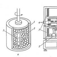 Basic technologies for obtaining nanomaterials
 How to tell the time in English?
 Introduction to Multivariate Statistical Analysis
 Presentation of the analytical report of the history teacher
 Presentation on the topic "atherosclerosis"
 History of number systems
 Apple in mythology and Russian folklore